HELP *** Burnt resistor of camera.

Thread Starter

TravisHC

Joined Oct 10, 2020
1
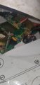
Well to start i am in no way an electrician or an engineer. Lol I'm just an old ironhead, im a ironworker and my hobby is electronics but I'm always working in the software side but as of lately I been dabling in the hardware side and got a soldering iron and everything needed with it I havnt used it yet but I'm in the process of learning and teaching myself along with studying what I can online about the hardware side of things and components. Well long story short I have this camera that has a burnt resistor and I'm unsure what kind it is cause its black lol I have a schematic sheet but its like reading Chinese to me....nothing like a structural steel blue print I'm used to haha....anyways its the perfect thing for me to practice on and to do my first solder job so can someone please tell me which resistor I need to fix this? Thankyou in advance for any useful input and sorry if this isn't posted within the right place.
 

Attachments

drc_567

Joined Dec 29, 2008
1,156
... Is there a transistor that seems to be connected to the burned resistor, or is in the vicinity? Usually, transistors are denoted with a Qxxx label. The idea is that the transistor has shorted, causing too much current to pass through the resistor, which would be the reason for its failure.
... A possible transistor to examine is Q102, which is connected to a 100 ohm resistor, R105. That particular transistor looks like a power transistor of some type, and would have higher current levels than other transistors in the circuit.
... Without additional details, this is only a guess, and could easily be incorrect.
 

AlbertHall

Joined Jun 4, 2014
12,345
The burnt resistor is connected to what looks like a connector of some sort - the black thing with four connections. What is that connector?
 

rsjsouza

Joined Apr 21, 2014
383
It is a bit hard to correlate the photographs with the schematics, but this seems located near a LCD and an ASIC blob (the black round blob under the yellow ceramic filter).

If the burnt part is connected to a power connector, it could well be either L102 or L103 - not a resistor but an inductor. Otherwise, if it is connected to the ANT1 or ANT2 (antenna), it could be the small squiggly line (also an inductor) near it.
 

sghioto

Joined Dec 31, 2017
5,380
The schematic is only showing the TX part of the unit. Still suspect it's the DC input jack.
Wonder where the TS got the schematic and does he have the rest of it. I haven't had any luck searching the web.
 

AlbertHall

Joined Jun 4, 2014
12,345
it could well be either L102 or L103 - not a resistor but an inductor.
That component (and I do think it looks slightly more like an inductor) is the only connection to that pin of the connector (if that it be), so that would seem to exclude L102 and L103.
We need the rest of the schematic.
 

rsjsouza

Joined Apr 21, 2014
383
That component (and I do think it looks slightly more like an inductor) is the only connection to that pin of the connector (if that it be), so that would seem to exclude L102 and L103.
We need the rest of the schematic.
Yes, although there is a connection on a pin on the back of this "connector" that leads somewhere else. My take is that we need not only the rest of the schematic but also better pictures of the surroundings and the back of the "connector"
 
Top