Facebook
 Google
 GitHub
 Linkedin
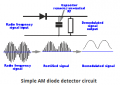
hello, can somebody help me? i found this am receiver, but is using variable capacitor,
how can i replace of do with varicap this circuits(i hava varicap bb112)

how can i replace of do with varicap this circuits(i hava varicap bb112)
Last edited by a moderator: