Facebook
 Google
 GitHub
 Linkedin
Hello all, hope everything is going great!
I would appreciate it if you guys can give some thought feedback on the following questions.
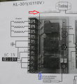
My good friend is trying to hookup a heater system. The schematic is the picture in black and white, and is attached down below.
My conclusions about the schematic / system are as follows:
1) I am pretty confident the black box with the Chinese characters and "110V" written on it is the power source.
2) L2 needs to be hooked up to a single hot wire coming in from the 110V "black box" power source.
3) L2 is going into the 3 ports ( which are in turn themselves individually labeled L1, L2 and L3 on the PCB, if you look closely on the board)
4) L1 needs to be hooked up to the neutral of the "black box" power supply line.
5) The third line coming out of the "black box" power supply line ( indicated by a green arrow) needs to go to ground
6) One wire needs to go from the top "G" terminal, marked by the red dot, to the ground wire mentioned in point 5 above.
7) Another wire needs to go from the bottom "G" terminal, marked by the blue dot, to the ground wire mentioned in point 5 above.
6) The hot wire coming out of the power supply and going into L2 needs to be attached to just one of the 3 screws, because the terminals are already connected through a copper jumper plate; as shown in the color picture below.
7) We should see three wires coming out of the power supply box. ( one hot, one neutral and one for ground)
Can you gentlemen please kindly put in your thoughts and tell me if my conclusions are valid, so that i can help him out? ( I am confident about my conclusions , but just want to double check so that i wont cause him a loss.)
Thank you very much for your replies.


I would appreciate it if you guys can give some thought feedback on the following questions.
My good friend is trying to hookup a heater system. The schematic is the picture in black and white, and is attached down below.
My conclusions about the schematic / system are as follows:
1) I am pretty confident the black box with the Chinese characters and "110V" written on it is the power source.
2) L2 needs to be hooked up to a single hot wire coming in from the 110V "black box" power source.
3) L2 is going into the 3 ports ( which are in turn themselves individually labeled L1, L2 and L3 on the PCB, if you look closely on the board)
4) L1 needs to be hooked up to the neutral of the "black box" power supply line.
5) The third line coming out of the "black box" power supply line ( indicated by a green arrow) needs to go to ground
6) One wire needs to go from the top "G" terminal, marked by the red dot, to the ground wire mentioned in point 5 above.
7) Another wire needs to go from the bottom "G" terminal, marked by the blue dot, to the ground wire mentioned in point 5 above.
6) The hot wire coming out of the power supply and going into L2 needs to be attached to just one of the 3 screws, because the terminals are already connected through a copper jumper plate; as shown in the color picture below.
7) We should see three wires coming out of the power supply box. ( one hot, one neutral and one for ground)
Can you gentlemen please kindly put in your thoughts and tell me if my conclusions are valid, so that i can help him out? ( I am confident about my conclusions , but just want to double check so that i wont cause him a loss.)
Thank you very much for your replies.
Last edited: