SCR-Controlled Heater Circuit

Thread Starter

ramolegbe

Joined May 7, 2025
2
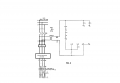
The Fig. 1 is a currently-existing heater circuit controlled by a on/off switch (N2) switch contact (dwyer 25013) controller from a "J" thermocouple. Due to frequent heater failure from too frequent cycling, the goal is to control the heater using a 4-20 mA controlled output from a dwyer 25015 controller into a phase angle SCR. It is also intended that a set of safety contacts replace the starter contactors (42>>>12) and also add a EMI filter downstream of the safety contactor. Fig. 2 is what i believe my new circuit ought to look like Fig. 2 Please provide feedback.Fig. 1.png
 

Attachments

schmitt trigger

Joined Jul 12, 2010
2,027
You don’t provide the load details….But, I would assume that being 3phase 480 V load, it is going to be a quite powerful load.
Therefore, the generated EMI would be very significant. The filter is going to be bulky and expensive. The powerline harmonics will also be a headache.
For heating loads is far, far better to use an integral cycle control strategy.
 

Thread Starter

ramolegbe

Joined May 7, 2025
2
Load is 45 KW heater bank. The Integral Cycle Control was considered and rejected on vendor recommendation. Thank you for your feedback.
 

MisterBill2

Joined Jan 23, 2018
27,172
Been there and done that! But it was a 5KW 480/3phase heater in a smaller oil tank. I used an ON/OFF time prppotioned control with 3 x 25 amp SSRs. (CRYDOM, I think) I think that the whole cycle was 5 or ten seconds, and the controller would switch the heater on for some portion of the whole cycle. A safety shutdown was a 3pole contactor controlled by an over-temp thermostat swich on the tank plus the overtemp output of the controller. It was a hot-oil life test machine so the oil was between 250 and 300 degrees F. It ran 24/7 for many weeks at a time.
 

Pyrex

Joined Feb 16, 2022
501
Hi,
Heating elements wear out the most in the first few minutes after being turned on, until they heat up sufficiently.
To reduce this stress, a switching circuit could be used, the same as the one used for three-phase motors, Delta-Wye.
When the command to turn on the heating elements is given, they are configured according to the Wye configuration, and after a few minutes they configured according to the Delta configuration .
A standard motor control relay can be used to perform such switching .
This kind of circuit is simple, reliable, and does not cause any harmonics in the powerline.
The start power is reduced by factor of 3
 

MisterBill2

Joined Jan 23, 2018
27,172
Hi,
Heating elements wear out the most in the first few minutes after being turned on, until they heat up sufficiently.
To reduce this stress, a switching circuit could be used, the same as the one used for three-phase motors, Delta-Wye.
When the command to turn on the heating elements is given, they are configured according to the Wye configuration, and after a few minutes they configured according to the Delta configuration .
A standard motor control relay can be used to perform such switching .
This kind of circuit is simple, reliable, and does not cause any harmonics in the powerline.
The start power is reduced by factor of 3
That scheme is often called "WYE-DELTA" switching and it requires more than justa single "3 pole N.O." contactor. I have used it for starting motors quite a few times.
 

panic mode

Joined Oct 10, 2011
4,864
4-20mA is a classic analog signals used for current loop. you need digital output to drive SSRs (zero crossing type) and that is what dwyer 25015 has (a relay output). the electromechanical contactor(s) should only be used for safety and why-delta switching. but should not be cycling. leave cycling for SSR.
 
Last edited:

MisterBill2

Joined Jan 23, 2018
27,172
Certainly "analog control" of the heater scheme would be the way to avoid simple on-off time proportional cycling. That is commonly known as "phase control" and it works quite well. BUT changing to phase control involves a lot more than just ON/OFF switching. As I reviewd post #1, that appears to be the plan. And that circuit drawing is rather misleading in that much of it does not relate at all. Indeed the application will continue to require a safety contactor, shown as "42" in that drawing, and at least two suitable SSRs , as I already mentioned. Probably also a DC supply for the SSR control devices. I would not consider creating the control devices myself because of the power level. That "dwyer 25015 controller" probably does not have three isolated phase control outputs, so you will also need a rather expensive analog triple phase controller with optical isolation .
But consider that frequent heater failures also indicate poor quality, or inadequate rating margins.
 
Top