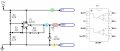
headphone amp powered by 19v adapter

Thread Starter

juggler73

Joined Apr 10, 2010
47
hi
i have a headphone amp that i got as a kit from ebay it works well for what i need it for but the problem is that the batteries dont last long and i was hoping to use a spare 19v 4740mA laptop adapter i have

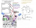
the amp runs off two 9v batteries and you can see by the picture 1 it not a straight forward connection.

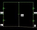
i was thinking that i would need to make a voltage divider seen in picture 2 and connect it as the batteries would connect.

does anyone have any advice on this working

thanks
 

Attachments

SgtWookie

Joined Jul 17, 2007
22,230
Oops - no, that's not going to work.

Fortunately, there's a pretty easy solution to your problem; it involves using an inexpensive power opamp.

But, first need to correct the rather non-standard way they decided to wire the power switch. I'm rather curious why they decided to switch both of the "virtual grounds" instead of the +V/Vcc and -V/Vee leads.
 

Thread Starter

juggler73

Joined Apr 10, 2010
47
hi
i forgot to say im only starting out in electronics so help is needed

how do i correct the wiring and whats an power opamp and then how would i connect it together

i would get a mains powered headphone amp but i cant find one thats a kit or a list of parts

thanks
 

SgtWookie

Joined Jul 17, 2007
22,230
OK, first off it's very helpful if you include your country in your profile - that way we can better suggest parts that you might be able to get easily. Click on the "User CP" link below the forum link to get to your profile settings.

Parts that are easy to get in the States can be rather expensive in Europe. For example, Asia has a very different system for transistors than we have in the USA.

I have various things going on, so this is going to be rather a step-by-step process.

First of all, see if you can find available an L272 or L2720 power opamp, and is it reasonably priced. These opamps are very inexpensive in the States, as they are widely used in automotive applications.
 
Last edited:

SgtWookie

Joined Jul 17, 2007
22,230
I clicked on your link; a whole list came up.

This one?
http://gb.mouser.com/ProductDetail/...GAEpiMZZMtCHixnSjNA6Gd6XD%2bkxe1piyzEnUqf3fI=
Mouser Part No: 512-L272AM, £0.382 each?
That should do the trick nicely.

When you go to place your order, it wouldn't hurt to have a couple extra on hand if you might be interested in doing some small electric motor projects in the future. However, don't order straightaway, as you will need a few more bits.

I need to finish making some changes to your original drawing that you posted, but I have to leave for a hour or so.
 

Thread Starter

juggler73

Joined Apr 10, 2010
47
i was just looking at the delivery and its £12 so it must be coming the US

so im looking elsewhere hopefully i can find some in the UK

thanks
 

SgtWookie

Joined Jul 17, 2007
22,230
Good find - you're set with that ;)

Sorry I'm a bit slow; have many irons in the fire, and many people want some help.

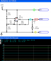
Here's how you can use the L272 as a "rail splitter":


For the unused opamp, you would simply wire the - input to it's output, and the + input to the output of this one. That way, it won't cause problems by oscillating on it's own.
 

Attachments

Thread Starter

juggler73

Joined Apr 10, 2010
47
hi
no worries dont apologize im glad for your help

what is this circuit actually doing is it dividing the 19v adapter but im not quite sure how to connect to my headphone amp.

pictures would be good

is R5 1ohm
how many volts is the C1 .22uf cap

thank you again
 

SgtWookie

Joined Jul 17, 2007
22,230
hi
no worries dont apologize im glad for your help

what is this circuit actually doing is it dividing the 19v adapter
R1/R2 form a voltage divider. At their junction will be 9.5v, when referenced to ground, or 19v/2 = 9.5v.

R3 and R4 are the feedback path. The output of the opamp will follow the noninverting input (9.5v) very closely.

R5 is 1 Ohm. C1 is 0.22uF, and should be rated for 25v or higher. R1 & R2 form a Boucherot cell, which helps to eliminate any tendency to oscillate. Boucherot cells are very commonly used in audio amplifier circuits.
http://en.wikipedia.org/wiki/Boucherot_cell

... but im not quite sure how to connect to my headphone amp.
I haven't finished modifying the image you posted.

The battery connections to the switch/board will need to be changed a bit.
It was goofy how they switched the two battery grounds rather than the + and - power rails.

Are you planning on leaving the batteries in while using your external power? If so, that will complicate things a bit.

pictures would be good
Pictures? Well, I don't have a unit like yours. You'll have to make do with drawings.

is R5 1ohm
Yes.
how many volts is the C1 .22uf cap
25v minimum.
 

SgtWookie

Joined Jul 17, 2007
22,230
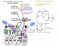
OK, compare this to your original.

I've changed the switch connections so that V+ and V- are switched instead of the grounds.

The board only needs one ground connection. You can see that the traces are connected.
 

Attachments

Thread Starter

juggler73

Joined Apr 10, 2010
47
hi

wow that looks great :)
ive got the stuff ordered and it come this week so i'll do it then

just one thing i need to check that i got the pin places right

thanks
 

Attachments

SgtWookie

Joined Jul 17, 2007
22,230
Nope - you have the Vcc pin labeled 6. That should be pin 2.

Don't forget that you will need to connect up the other opamp to keep it from oscillating.

Pin 5 to Pin 3
Pin 6 to Pin 7 (it's OK to use the same reference as the other opamp)

You should also have an 0.1uF cap across the Vcc/GND pins of the L272. Having a 100uF cap across the +19/GND inputs will help to keep things quiet.
 

Thread Starter

juggler73

Joined Apr 10, 2010
47
hi

i'll get back to yer when i got it going and if i have any problems when i got it all soldered together

thank for your help :)
 
Top