headphone amp powered by 19v adapter

SgtWookie

Joined Jul 17, 2007
22,230
I hope you'll like using it.

Note that there are two different stripboards available, all the way at the bottom of the list.

It doesn't matter if they aren't exactly the same as what you will be using - just so you can get the layout down.

It may seem inconvenient to only be able to orient things horizontally or vertically, but that helps prevent things from getting messy.
 

Thread Starter

juggler73

Joined Apr 10, 2010
47
hi

i wanna make sure i got the right capacitor the .22uf one

what type do i need Polyester or Electrolytic

i have Electrolytic with 22uf 25v on the side but im thinking there not right ones so i thought i better check.

thanks
 

SgtWookie

Joined Jul 17, 2007
22,230
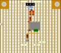
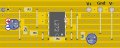
That looks rather messy.

Don't forget that you will need to cut some of the traces in the stripboard to make it work; particularly the traces that run under the opamp.

Metal poly film is a very good type to use.
Ceramic is OK.
You need 0.22uF. You could use a 22uF in parallel if you would like, but you need the small capacitor to make sure that high frequency oscillations don't occur.
 

Thread Starter

juggler73

Joined Apr 10, 2010
47
hi
ive got a .22uf metal poly rated at 275v can i use that?

also is there a better to do this stripboard any tips would be great :D

even though it was rather messy was it right?

i know that under the op amp i would need to cut the traces but where else?
 

retched

Joined Dec 5, 2009
5,207
You will need to cut the traces between each vertical components leads. For instance, the resistors you have running north to south, you need to cut the traces BETWEEN the leads, under the resistors. If you do not, the electrons will run AROUND the resistor rather than THROUGH them.

 

SgtWookie

Joined Jul 17, 2007
22,230
No, it's not.

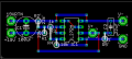
What is C1? I didn't have that on my schematic. I'll bet your C2 is the one I had on my schematic as C1.

You need to keep the reference designators the same on your stripboard as I had in my schematic.

You have an inverting input tied to ground. It's not going to work like that.
 

Thread Starter

juggler73

Joined Apr 10, 2010
47
hi
you said "Having a 100uF cap across the +19/GND inputs will help to keep things quiet"

thats what c1 is.

"inverting input tied to ground" where have i done this

please help
 
Last edited:

Thread Starter

juggler73

Joined Apr 10, 2010
47
hi

got it all soldered up and its working

The voltage coming out of the adapter and it was 19.60v before and then checked V- and V+ and got 9.69v on V+ and 9.89v on V-

is that ok?

thanks
 

SgtWookie

Joined Jul 17, 2007
22,230
Well, using the GND terminal as a reference, your V+ should measure roughly +9.8v, and your V- should measure roughly -9.8v, +/- 5%. (9.3v to 10.3v)

If you are measuring +9.89 on your V-, you have a problem.
If you are actually measuring -9.89 on your V-, then all is well.
 

SgtWookie

Joined Jul 17, 2007
22,230
OK.

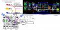
Remember that in the diagram I posted, by the right electrolytic cap, the black wire from the switched V- goes to the LOWER pad, not the UPPER pad.
 
Top