Having problems with thyristor commutation circuit

Bordodynov

Joined May 20, 2015
3,431
startup sets the zero value of the voltage to voltage sources at zero time and after 10 μs these voltages will take their meaning.UIC allows you to set the initial value of the voltage on the capacitor, for example C11 4 0 100u ic = 20.For inductance, you can specify a current, for example L6 3 4 100mA ic = -100mA.You can also specify a voltage in any node of the circuit, for example .ic V (7) = 3 v (2) = - 1. Thus, one can not wait until the stabilizer (or rectifier) charges the output capacitors (i.e., reduce the time that the circuit enters the stationary mode). It can also help improve the convergence of the calculation.
 

Thread Starter

radityaar

Joined Jul 2, 2018
17
startup sets the zero value of the voltage to voltage sources at zero time and after 10 μs these voltages will take their meaning.UIC allows you to set the initial value of the voltage on the capacitor, for example C11 4 0 100u ic = 20.For inductance, you can specify a current, for example L6 3 4 100mA ic = -100mA.You can also specify a voltage in any node of the circuit, for example .ic V (7) = 3 v (2) = - 1. Thus, one can not wait until the stabilizer (or rectifier) charges the output capacitors (i.e., reduce the time that the circuit enters the stationary mode). It can also help improve the convergence of the calculation.
Thank you for the explanation!
 

ebp

Joined Feb 8, 2018
2,332
I can see no mechanism for charging the cap when the main thyristor is on - there is no path for current. The only potential difference across the cap and the inductor is the forward voltage of the SCR [EDIT] and the path is blocked by the diode.

Run a sim with the cap discharged at the start and look at the current (ALWAYS look at currents - I've seen many many sims at AAC where people can't figure out what is going on because the currents aren't examined). The cap will charge when the commutating SCR is turned on.
 

Thread Starter

radityaar

Joined Jul 2, 2018
17
I can see no mechanism for charging the cap when the main thyristor is on - there is no path for current. The only potential difference across the cap and the inductor is the forward voltage of the SCR [EDIT] and the path is blocked by the diode.

Run a sim with the cap discharged at the start and look at the current (ALWAYS look at currents - I've seen many many sims at AAC where people can't figure out what is going on because the currents aren't examined). The cap will charge when the commutating SCR is turned on.
You're right, using initial conditions of discharged capacitor, the plot shows the current flows only when commutating thyristor is on. Does adding a resistor next to the capacitor solve the issue?
 

ericgibbs

Joined Jan 29, 2010
21,567
hi radir,
My post #18 shows starting with Vsupply=0 the 1uF[100uF] cap does not charge.
Where did you get the circuit design.?
E
 

Thread Starter

radityaar

Joined Jul 2, 2018
17
hi,
Look at this option, its driving an Res/Ind load, 20mS rate.

E
hi Eric!
your plot seems to show that the first thyristor is not conducting properly(decaying gradually rather than conducting continously until the second thyristor is turned on)
 
Last edited:

ebp

Joined Feb 8, 2018
2,332
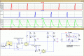
It looks to me like the hold current threshold is not being met in the plots at 29. 250 mH with a 10 V source makes for a pretty low current slew rate, even without a series resistance I suggest reducing the load inductance or increasing the supply voltage. It would be helpful to show the actual gate trigger pulses for timing reference.
 

ericgibbs

Joined Jan 29, 2010
21,567
hi radit,
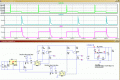
This sim works OK, its important that the 10uF is charged before the first Tt pulse. [this why the sim fails when .tran startup is used]
In your actual circuit you have to pre-charge the 10uF to 10v before triggering the Tm SCR.
Look thru this video, it shows Class D commutation.


E
 

Attachments

ebp

Joined Feb 8, 2018
2,332
To precharge the capacitor, fire the commutating SCR before firing the main SCR. It could also be precharged by adding a resistor between the bottom end and the negative of the supply, but the resistance would need to be quite high to prevent excessive discharge of the cap during the ON time of the main SCR.

The video glosses over an important aspect:
Assuming the cap is charged with the top end positive, when the main SCR turns on the cap discharges through the inductor and the diode - it can't go anywhere else. The energy thus stored in the inductor is then transferred back to the capacitor (again, nowhere else for it to go), making the bottom end of the cap positive with respect to the input positive supply. There are losses due to the forward voltages of the SCR and diode.

If the timing of the sim is fixed to shorten the long "dwell" times and reduced to only a couple of cycles, and the capacitor and inductor voltages and currents are added, this will become apparent. The currents are already there as the big spike when the main SCR turns on, but the detail can't be resolved.
 

ericgibbs

Joined Jan 29, 2010
21,567
hi r,
Could you give more details about the project that the comm'' circuit driving.?

Update:
How are you generating the Tm and Tm 'otpo' drive pulses in the actual circuit, MCU etc.???

EDIT:
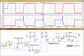
This sim shows one sample option for pre-charging the 10uF cap.
 

Attachments

Last edited:

Thread Starter

radityaar

Joined Jul 2, 2018
17
Thank you everyone for all the information!
@ericgibbs Yes, I have also tried turning on the second thyristor first and it works but couldn't update on the thread because my internet was dead the whole day:(. I'am actually generating the pulse manually through a push button without a MCU exactly like the simulation at the moment.

@ebp is there any way to compensate for the voltage drop across the thyristor and diode?
 
Last edited:

ebp

Joined Feb 8, 2018
2,332
I can't think of any simple way to usefully compensate for the voltage drops. The drops shouldn't be a problem unless the supply voltage is so low that the voltage left on the capacitor is too low to assure commutation. As long as the voltage and charge on the capacitor is sufficient to produce reverse bias on the man SCR for sufficiently long to cause it to turn off, all should be OK. It actually isn't really necessary to reverse bias the main SCR - just get the current through it reduced to below the minimum holding current for long enough, but producing reverse bias assures some margin beyond the minimum requirement.
 

ericgibbs

Joined Jan 29, 2010
21,567
hi radit,
Regarding pre-charge of the Cap, as a test in your circuit, I switched the Ta [t3] first before sending the Tm/Ta comm pulse sequence.
By sending a longer period Ta pulse first, the Cap was charged in readiness for the first Tm[t1] pulse.
Once you have the project under MCU pulse control, it would be easy to produce the pre-charge Ta pulse.
If it works in the actual circuit as it does in simulation, you could drop the hardware pre-set [ FET & R/C] components.

E
 

Thread Starter

radityaar

Joined Jul 2, 2018
17
hi eric,
The circuit finally works!I An important aspect to keep in mind is the time between the firing between the first and second thyristor. I realized the voltage of the capacitor decreases when I turn on the first thyristor, thus the second thyristor has to be fired quickly to ensure enough voltage is used for the commutation. I also added a 1 ohm resistor between the bottom end of the capacitor and the second thyristor. Adding an MCU would make this much easier as you said
 
Last edited:

ericgibbs

Joined Jan 29, 2010
21,567
hi radit,
Thats good news, well done.!;)
It will be interesting to see your completed project, when ready.
I guess you know we have a Completed Projects Forum at AAC.?
E
 
Top