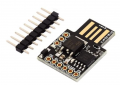
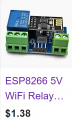
How do you interface that cute little module with the mains powered motion sensor?? an then have it switch the alarm device? and while the time setting can be flexible, the setting knob seems to be missing. Sort of like a good racing engine witout a racecar to drive in.
any way you like. optocoupler comes to mind. or ... why even bother with some AC powered PIR when one can get cheap one that is meant to interface with MCUs - like in above mentioned kits?
also using relay your alarm can be anything you like.
about setting knob, that is the beauty of using MCU. you can use keypad, encoder, potentiometer, set of DIP or BCD switches... you can have LCD display for feedback co couple of buttons would do. all of those things are explained in the instructions already linked.
personally i would just connect it to a computer via USB to set the time.
My points exactly, a collection of parts that needs a computer and a whole bunch of wires and then a package to mount all of the little pieces and it still would not be as durable as the original concept. And probably not UL approved, either.
The suggestion in post #3 would seem to solve your problem. This is one possible time switch that would solve your problem. The set of contacts has no connection to the timer power supply so they can just be connected between the PIR output and the alarm sounder. I have seen versions of this type of timer that will work from a 230 or 120 volt AC supply. I have also obtained timers requiring a 230 volt AC supply available localy with the contact connections available from either Toolstation or Screwfix. I bought one of these over 10 years ago from one of these supplier but have not looked to see if they still available.
My points exactly, a collection of parts that needs a computer and a whole bunch of wires and then a package to mount all of the little pieces and it still would not be as durable as the original concept. And probably not UL approved, either.
for some reason you seem to feel very strongly about this and have need to criticize any option that is beyond your understanding or capabilities. don't you think TS should get the information and decide for himself? try to keep an open mind.
just to clarify - computer is one option (I like to make things really small) but it is not needed except to put program into MCU.
there is no bunch of wires. it could be zero wires if one chooses to use shields for example. they literally snap together into a solid brick with no extra wires. with commonly available $20 parts one can get something with LCD (even in RGB) several buttons (more than enough to set parameters) and not one but four relays. there are pluses and minuses to every solution but it may not be a bad idea for someone with no experience in wiring to pick common and of the shelf part and only mess with few lines of code of ready made examples. in other words it is something easy to reproduce and support even without looking at particular construction. and the entire thing is low voltage, safe to experiment with.
if one needs to connect it to mains it is not a problem since it does have relays and wall-wart power supplies are everywhere.
finally i fail to see the point in comparing durability of popular products with tremendous amount of support and documentation, sold in millions with some unknown origin products found only on eBay. btw TS is talking about 220V circuit so clearly he/she is not in North America. so wherever TS is, UL approval there means nothing.
again, i like to make things really small. so my idea is to make things tiny and controlled through web. something an ESP01 relay would be capable of.
In this thread the TS was asking about connecting what seemed to be off the shelf mains powered items, to provide a rather simple functionality. The original concept was a string of plug-together items where the entire sequence of assembly could be described in one sentence. Those items could all come from a reasonable hardware shop or home improvement store.
It was fairly clear that the TS was not a master tech, nor seeking to become one, although I might be wrong about that part.
The one requirement did add the need for a different sort of time switch, which suddenly altered the hardware list by adding a relay switch. But none of this required dealing with circuit modules from on-line suppliers. Quite possibly the needed relay could be purchased from some hardware stores, similar to one in my area. So there is a massive difference in the complexity between what was requested and what was suggested.
Actually no, he wanted to supply power to the entire system only from midnight to 4 AM, and suppress an alarm at power up. That cannot be done with a simple on-off timer.
The simple solution is to leave the system always powered and use a timer to connect the alarm system to the PIR only during those hours, but it might be unacceptable to power them always.
I have been fascinated by the variety of approaches suggested!
I'm awaiting delivery of a couple of items before building a prototype setup.
I'm not necessarily looking for a miniaturised system and at my age I don't want to learn all about Arduinos. I just want to use off-the -shelf items even if some of them run 24/7 eg a plugin 220v timer and a 220v PIR because I find mains voltage PIRs to be better.
The PIR will will connect to a relay which will close a NO contact that will allow current from the timer when it is active between 00:00 and 04:00am. This current will trigger another "timed off relay" (after 10 seconds) which will switch on the 12v DC supply to the alarm for 10 seconds. The second relay will not be needed if I can get a timed off relay that works on 220V.
I should have it set up in 2 days.
All of the mains powered PIR light controllers that I have a test mode that does not hold the light on after it is triggered. If a time shorter than ten seconds might be acceptable that could avoid needing a separate ten second timer. That could be a real benefit.
You’re 00:00 to 04:00 will be the difficult part, unless the circuit has a reference. An RTC could give you an enable / disable signal, esp32 could query a time server. A micro with a true RTC could be used. Accuracy may not be the point, but drift will require reset at some point. Depending on the need to disable, there may be other sensations that could be conditioned.
Really if you want quick and simple and in the event of mains failure you don't mind resetting the time something as simple as this will do just fine. Since I am in the US you see 120 VAC 60 Hz but I am sure wherever you are they have the same. You simply place a mains voltage, for your location, at the output. Yes, you can find all sorts of more complex solutions like RTC (Real Time Clock) solutions. All you need is a simple off the shelf relay with a coil rated for your mains voltage. Relay energizes during your preset times closing the normally open contacts passing along your PIR sensor output.

 Facebook
 Google
 GitHub
 Linkedin