Hall Sensor

Thread Starter

AMJC77

Joined Apr 2, 2015
13
Hi I am using a Hall Sensor or Current Sensor transducer for a project in college. This is the link for the component here >http://ie.farnell.com/honeywell-s-c/csla2dj/current-sensor-transducer/dp/1703967?ost=1703967

The rating of the Sensor is 8V - 16Vdc & max current at 255 Amps. I calculated it earlier that I get 11mV per 1 Amp we measuring current from the wire of a heat sink.

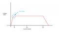
I am just wondering if any body would be able to source a linearity scale for me. I have been looking the last 2 days for one on the web and cannot find one. The linearity scale I am looking for is for Voltage vs Current.

Thank you.
 

MaxHeadRoom

Joined Jul 18, 2013
28,576
What means of display do you need, there are a few custom methods of indicating the result, you may find a digital display from Red Lion controls that would do the job.
Along the lines of a digital voltmeter, that is scalable.
Max.
 

Reloadron

Joined Jan 15, 2015
7,480
There is no linearity scale that I am aware of for that sensor. Where did you get this:
The rating of the Sensor is 8V - 16Vdc & max current at 255 Amps.
The sensor is a 225 Amp AC or DC sensor. The sensor should be powered from 6 to 12 VDC. The only sensors in that family using 8 to 16 VDC are CSLA1GD, CSLA1GE and CSLA1GF which are 57, 75, and 100 Amp sensors, not the sensor you mention. The output of these sensors is linear and the output will be a function of your supply voltage:

CS Series current sensor holder assemblies
have a single linear output that will
source current. The output voltage, which is
ratiometric, varies in direct proportion to the
supply voltage.
The output offset voltage will be Vcc/2. Since the output is a function of Vcc there is no output table. This is a link to one of several data sheets out there.

Ron
 

MaxHeadRoom

Joined Jul 18, 2013
28,576
This model shows 8.7mv -(number of turns) at 8vdc.
It is ratiometric so depends on the applied voltage.
I still think a suitably scaled & calibrated digital voltmeter unit should work.
Max.
 

Thread Starter

AMJC77

Joined Apr 2, 2015
13
Excuse me, you're right the rating for the CSLA2DJ sensor I have is 6V-12V, I pasted in the wrong votage, apologies. This is the datasheet I have for those of you who asked > http://www.tme.eu/en/Document/43ec50c727d976bb1fe88e38263c5b1d/CSLA.PDF It does not contain a linearity scale.

Yesterday in our lab we had the sensor hooked up to a 5V supply, our output was 2.5V. I (with my lecturer) then varied the voltage into the heat sink, starting low - high. At one stage I was getting 4Amps at roughly 60V, which read about 2.54 on the multimeter I had. Unfortunately we don't have a digital multimeter in our college so the reading was only accurate to one decimel place which isn't very accurate.

However, talking to one of my lecturers he told me that Voltage vs Current scale for this sensor is not completely linear. My lecturer is now away for the next week and I am not aloud to further carry out this test with the heat sink and sensor on my own due to health and safety. This is why I am wondering if anyone may have seen one of these scales on the web.

I was only putting 4 Amps through the Sensor which is about 2% of its capability, I understand this.

Thank you for your replies.
 

Reloadron

Joined Jan 15, 2015
7,480
OK what you saw is normal. While power should be 6 to 12 volts you had a Vcc of 5 Volts applied. Without any current through the loop the output should be 2.5 Volts (The data sheet says Vcc/2 so 5 / 2 = 2.5). The data sheet also mentions what I quoted above:

CS Series current sensor holder assemblies
have a single linear output that will
source current. The output voltage, which is
ratiometric, varies in direct proportion to the
supply voltage.
There is no chart, note the bold print above, there is no chart! Since the output is ratiometric and varies with the supply voltage there cannot be a chart. The data sheet does tell you that with a Vcc (Supply Voltage) of 8.0 VDC the output voltage will be about 8.7 mV per Amp with a single conductor passing through the loop hole.

Yesterday in our lab we had the sensor hooked up to a 5V supply, our output was 2.5V. I (with my lecturer) then varied the voltage into the heat sink, starting low - high. At one stage I was getting 4Amps at roughly 60V, which read about 2.54 on the multimeter I had.
OK, your supply voltage was low but with zero current your output was 2.5 VDC, exactly what it should be. When you had 4 Amps of current (voltage means nothing on your load) you measured 2.54 Volts. So what do you get from that? I see a .04 volt increase or about 4 Amps is 40 mV so .040 / 4 = .010 or about 10 mV per Amp. A little over the 8.7 mV mentioned above. There is no chart! You can search the web and the seven seas but there is no chart so stop looking for a non existent chart. I also assume the current you measured was DC? If you measure AC current the output of the sensor will be AC. The output will be AC riding on a Vcc / 2 DC offset.

Exactly what part of all of this are you not understanding?

Ron
 

Thread Starter

AMJC77

Joined Apr 2, 2015
13
When we turned up the voltage of the heat sink to 60V, we got a 4 amp output. We put this wire feeding the heat sink through the sensor and read out 2.54Vdc. Like you said when there was no load, it was 2.50Vdc. My lecturer gave me this forumla, Vdc/Max current = 2.5/225 = 11mV per Amp.

So the 2.5Vdc (Vcc/2) + 44mV (4 Amps from heat sink) = 2.54Vdc.

I am not too sure where he got the forumla from but it was accurate when I measured it with my multimeter. I could not understand why 5 was used either. I will ask him when he gets back.

I don't know whether I am saying it right or not but this is the rough diagram I was drawn by my lecturer for Voltage s Current. I posted the picture below.
He was basically trying to tell me that as you turn up the voltage the current will climb linearly until a certain point (max voltage I imagine), stay constant and then fall off after max current is exceeded. But at one point, roughly at 1% or 2% the climb in current is not completely linear. I pointed at this area on my graph with a circle.

If this graph does not exist, thank you for your help any way!
 

Attachments

Top