It's a car throttle pedal, which I want to repurpose for a TIG welding pedal to control the weld amps.
Inside the pedal there is a magnet travelling against a sealed sensor, and on the bench I'm getting the results mentioned above. With a 6v feed from a bench power supply, the output varies between 5 to 1.2v.
On the welder side, it's a simple pot control port with a 6v feed. When a potentiometer is added, the range is of course 6 to 0v, but the relevant travel that affects a change is actually 5 to 0.5v. With the pedal plugged into the machine (in theory, haven't put it in yet), the upper limit matches perfectly at 5v, but the lower limit bottoms out a little too early at 1.2v. A little more physical travel of the pedal would have given me the extra down to 0.5v, but it's not possible without major hacking - if at all.
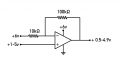
Here is a circuit based on MrChips suggestion, using an op-amp configured as an inverting amplifier.
The non-inverting input of the op-amp is biased at 3V by the two 10kΩ resistors. The gain is set at 1.5 by the input resistor (22kΩ) and the feedback resistor (33kΩ). The circuit response is as follows:-
Input voltage Output voltage
1.2V 5.25V
2V 4.5V
3V 3V
4V 1.5V
5V 0V
Since the circuit is inverting, the input pot needs to be wired in reverse such that at the maximum setting the pot output voltage is 1.2V and at minimum 5V.
Almost any ‘common or garden’ op-amp should suffice – even a 741.
My circuit idea would be more complex, and possibly required a dual rail voltage.
OK, simply add a unity gain inverting op-amp to the output of circuit.
With 8 pin packages containing 2 op-amps available, it will add minimal additional components.
The second inverting op-amp would be configured exactly as the first, except that the input and feedback resistors would both be 10kΩ, resulting in inverting unity gain. To correct for the fact that the output voltage is not equal about 3V, the voltage divider resistor connected from the non-inverting input to 0V should be reduced to 6.8kΩ (from 10kΩ).
Adding filtering will prevent any electrical noise from the hall sensor appearing on the circuit output.
The easiest way of achieving this is to place a capacitor between the inverting input terminal of the second op-amp and 0V.
A value of 10µF will result in a time constant of around 1/10th second, which will provide a good level of noise rejection without compromising the circuit’s speed response to the hall sensor input signal.
If using an electrolytic capacitor, ensure that the positive terminal is connected to the op-amp inverting terminal.
Unless you want an OFF/ON output DO NOT use a comparator. Use a non-inverting opamp circuit with an offset adjustment and a gain adjustment. I see that you have already been given the exact values, no need for me repeat that part.
Since the output is to control a welder current setting you will need to remove high frequency noise, and that may come from the hall effect device. So the filter capacitor would be on the INPUT side of the opamp. And you can put a capacitoracross the feedback resistor to reduce the AC gain. That is a valid approach.
There is a rheostat and a heavy duty pot. They are fairly hefty that is they are rugged and use sufficient current to overcome
ruff and tumble found under a welding table of a metal shop which include metal dust and stray magnetic fields heavy duty transformers and cables might even be a hall effects worst nightmare. There is a free online simulator that you could
throw together a few variable resistors and get the exact design values that you would need. https://www.multisim.com
It all needs to be enclosed in at least 10 gauge mild steel enclosure with a shaft being able being beat with a 5 lb hammer and dropped and run over the cable also large. A simple simulation and a ammeter reading and voltmeter would give the information needed for example let's say a 25 Watt 100 ohm rheostat and adjustment pot is what is called for then the criteria for the new circuit would use that information to replace what welding machine companies over many years been maintaining.
Certainly the ability to work with the rest of the circit is a requirement. I had guessed that the requirements had already been verified. If that is not the case then the rest of the project will be verifying that the op-amp circuit is able to provide the control current as well as the correct voltage.
And the mechanical ruggedness of the physical arrangement must be adequate for the application. Sparky describes a package able to stand up to considerable abuse, but nobody working for me would be allowed to abuse equipment that much. But certainly the enclosure must provide your electronics with adequate protection.
 Facebook
 Google
 GitHub
 Linkedin