 Facebook
 Google
 GitHub
 Linkedin
hi hgmjr.
well i am back to show you what i am doing. but first things first.
i managed to blow all my HE switches ( no surprise there). luck for me i have some OPB 876 optic transistors laying about, so i have had to connect up a new circuit as you see in the picture. if you would be a gentle man again and help me on my new circuit.
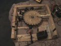
the second picture is off my disk ( a very nice job, if i may say so myself, in making it) the primary coil is small but should give a good kick. i have placed 4 AIR coils on the out side of the disk gauge 24.
i have got the 4 coils connected and then through a full bridge recifier.
i am getting out 9.50 volts DC at 75 RPM.
i get 18 volts spinning the disk as fast as i can with my finger. i know that it can go much faster and make alot more power.
so how about it! together we can make this work. i can buy most parts needs if another circuit need to be build.
i was thinking about using a IR emitter and IR detector as the sensor, which would be the best one.
if need be a 741 op amp circuit, all ideas are welcome
amps
well i am back to show you what i am doing. but first things first.
i managed to blow all my HE switches ( no surprise there). luck for me i have some OPB 876 optic transistors laying about, so i have had to connect up a new circuit as you see in the picture. if you would be a gentle man again and help me on my new circuit.
the second picture is off my disk ( a very nice job, if i may say so myself, in making it) the primary coil is small but should give a good kick. i have placed 4 AIR coils on the out side of the disk gauge 24.
i have got the 4 coils connected and then through a full bridge recifier.
i am getting out 9.50 volts DC at 75 RPM.
i get 18 volts spinning the disk as fast as i can with my finger. i know that it can go much faster and make alot more power.
so how about it! together we can make this work. i can buy most parts needs if another circuit need to be build.
i was thinking about using a IR emitter and IR detector as the sensor, which would be the best one.
if need be a 741 op amp circuit, all ideas are welcome
amps
Attachments
-
 133.5 KB Views: 21
 -
 149.7 KB Views: 16
 -
 134.1 KB Views: 16
Last edited:


