hall effect switch problems

Thread Starter

jasonspinmaster

Joined Mar 1, 2008
57
Hi All,
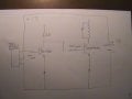
i am building a pulse motor and i am using a hall effect switch to fire the coil.
if i remove the power transistor and replace it with LED to positive the led flashes when a magnet pass the (HES).
when i conet up the power transistor a (2SD729H), nothing happens.
when i remove the doide from the power transistor, the transisitor saturates and stays on,
if i remove the 1Kresistor nothing happens in the ciruit.when i replace it again the transisitor saturates, i have tryed with a few resistors but wityh no luck i am finding it really hard to do the calulations for the resisitors and i have run out off ideas , can some one please help. i bought myself an oscilloscope a HAMEG HM604 but i do not know how to use it properly. i can see the pulse, so can any one help on the oscilloscope i would be very grateful.

jason
 

Attachments

mik3

Joined Feb 4, 2008
4,843
I can see that you are missing some connections on the circuit.
Please give us a link to the hall effect sensor datasheet as we can help you.
 

Thread Starter

jasonspinmaster

Joined Mar 1, 2008
57
hi there. i have a problem that i do not know the make. one i found in a box
i think it has an internal resistor off 30k???
i do not have a problem buying new ones that will work on the motor
i do have two RAZTEC hall effect sensors NEW
 
Last edited:

hgmjr

Joined Jan 28, 2005
9,027
OK. Assuming the RAZV-2 device is the component labeled "Hall Effect Sensor" shown in your diagram, then I am a bit confused.

From the sketch and the description in your initial post, it looks like you are trying to use the RAVZ-2 to output a pulse when a magnetic passes by the HALL EFFECT sensor. I don't think that the device is intended for use in that manner. The device is intended for applications that need to monitor a current.

It would be helpful if you could label the pinout of the HALL EFFECT device. Maybe I am missing something or your sketch is missing a few additional details.

hgmjr
 

hgmjr

Joined Jan 28, 2005
9,027
OK. Assuming the RAZV-2 device is component labeled "Hall Effect Sensor" shown in your diagram, then there are a couple of comments that I have regarding your circuit.

From your initial post it sounds like you are trying use the RAZV-2 to output a pulse when a magnet passes by the HALL EFFECT sensor. I don't think that the device is intended for use in that manner. The device is intended for applications that need to monitor a current.

hgmjr
 

Thread Starter

jasonspinmaster

Joined Mar 1, 2008
57
sorry i did not explain properly.
the hall effect switch i am using is the A45L, as in the picture
i have a the RAZTEC but it is not connected. i just thought i could use it.
 

Attachments

hgmjr

Joined Jan 28, 2005
9,027
OK. Now that we have that clearly established. Here is a link to the data sheet for the HALL-EFFECT sensor you are using. It appears to be made by INFINEON. Part number is TLE 4945 L.

hgmjr
 

Thread Starter

jasonspinmaster

Joined Mar 1, 2008
57
thank you for the data sheet.
but i am still a little lost on , if my circuit is correct? and about what resistors to use, could you please help me, i am willing to learn.
 

hgmjr

Joined Jan 28, 2005
9,027
I notice diodes in the emitters of the two transistors. Can you tell us what type of diode they are and what their intended purpose is?

hgmjr
 

Thread Starter

jasonspinmaster

Joined Mar 1, 2008
57
the diodes are 1N4001. i place them in they copying someone else circuit.
when i remove the diode from the power transistor the transistor saturates and stays on. i think i am correct in saying that with a diode i loose 0.6 volts
 

SgtWookie

Joined Jul 17, 2007
22,230
You couldn't remove the diode from the emitter of the power transistor without removing the diode from the emitter of the other transistor first.

If the output of the Hall-effect sensor goes below 0.6v, then you could remove both of the diodes.
 

hgmjr

Joined Jan 28, 2005
9,027
Looking at the circuit as configured, here is what it appears you are trying to do.

Assuming that the magnet is not near enough to the HE sensor to trigger it then the follow circuit state would exist. For the time being let's assume that the 1N4001 diodes are out of the circuit. They should not be needed anyway.

Transistor BC548 will be in saturation due to the injection of base current that is provided by the HE sensor. This means that the BC548's collector will be at around 0.2 volts or very nearly ground. Remember I am assuming that the diode in the emitter is eliminated. With the collector of the BC548 near 0 volts then the output power transistor should be turned off. With the power transistor turned off then its collector load is not driven and therefore the relay (if that is what the power transistor is being used to drive) should be unenergized.

The use of a 100 ohm resistor between the output of the HE sensor and the base of the BC548 is far too low in resistance value. A 10K resistor would probably serve in its place quite well. You will need to lose the 1N4001 diode in the emitter of both of the transistors.

With the magnet in close proximity of the HE sensor then the its output voltage should grop to nearly 0 volts. This should then turn off the BC548 whose collector voltage would then switch from near 0 volts to a little less than 1 Volt (again this is assuming that the 1N4001 is removed from its emitter). This will cause the power transistor to turn on and energize the coil in its collector. As long as the magnet is triggering the HE sensor then the coil will be energized. If this conditon is allowed to persist, I suspect that the coil heat up.

Does that sound about right to you?

hgmjr
 

Thread Starter

jasonspinmaster

Joined Mar 1, 2008
57
i have removed both diodes from the circuit and i have replaced the 100ohms resistor from the sensor the base to a 10K.
i am getting 0.11 volts on base and it drops to 0.01 when stopped over a magnet
the collector is 2.26 volts and does not move when a magnet is placed over the sensor and is saturating the power transistor
 

hgmjr

Joined Jan 28, 2005
9,027
Have you measured the output of the hall effect sensor directly with and without a magnet near it? That would establish that the sensor is functioning normally.

hgmjr
 
Last edited:
Top