Half dipole antenna - stainless steel wire with copper wire twisted around it?

MisterBill2

Joined Jan 23, 2018
28,502
I spent time in the 70's-80's on a several communications ships and stations often with HF transmit and receive antennas in close (several hundred few at most on ships) proximity. Because of the wide-band coverage needed we seldom used resonant standing wave antennas.
http://empossible.net/wp-content/up...g-Wave-and-Frequency-Independent-Antennas.pdf

https://www.navy-radio.com/ant/ant-lph2.JPG
Fan wire antennas.
https://www.navy-radio.com/ships/ffg7/ffg39-ant-fan.JPG
Certainly antennas optimized for broadband operation can work fairly well, no question about that at all. But every antenna is created for some parameter. and usually optimized for that parameter. That might be size, cost, gain, or frequency range, or maybe portability. Most are not the best at everything.
A receiving antenna does not need to be able to handle power, normally. A non-resonant antenna is able to be adjusted to provide satisfactory performance on some spread of frequencies,
 

Thread Starter

ApacheKid

Joined Jan 12, 2015
1,762
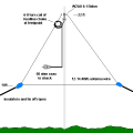
The width across the roof is pretty much 25m, if that's the length of a half-wave dipole then λ is 50m which represents 6MHz.

Apparently integer multiples of that would show a peak "gain" too so 12, 18, 24 and 30MZh would all be accommodated.

But I can equally just run single "long wire" across too, 25m single wire (insulated at the ends of course).

With that approach would one end of the wire become the center of a coaxial downlead and would I attach the braid, at the roof end, somehow to the building? itself?

Naturally I'd want to avoid attaching that to the electrical ground because of noise.

I could try the single "long" wire first then try the dipole arrangement.

To do that I'd simply attach the mounts at each end to the building, then run a single wire across and attach that (somehow) to a down lead and into my workshop.

I could explore that, assess the radio's performance for a few days and then cut the wire in the center, setup the coax connection to the center perhaps with a balun and again assess that for a few days.

The above would see the wire running East-West.

North and East of me are rugged Arizona mountains for hundreds of miles with almost no towns or anything.

South and East is much more populated, the East being much denser than the South.

The South has Tucson and so on, then Mexico, but relatively lightly populated compared to West of me, so having max sensitivity in the North-South direction seems sensible.
 

Thread Starter

ApacheKid

Joined Jan 12, 2015
1,762
Gotta say this "balun" has always been a mystery to me, even when I was I was in college studying electronics, radio etc I'd see mention of it here and there but never really did understand it.

The terms "balanced" and "unbalanced" are a bit vague to me too, what is this all about?
 
Last edited:

MisterBill2

Joined Jan 23, 2018
28,502
I can help with "Balun" quite a bit. First, cons
Gotta say this "balun" has always been a mystery to me, even when I was I was in college studying electronics, radio etc I'd see mention of it here and there but never really did understand it.

The terms "balanced" and "unbalanced" are a bit vague to me too, what is this all about?
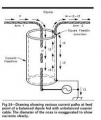
Consider a coaxial cable, which is a shielded wire. Now put that wire into the real world where nearby is some grounded conductive object. So two conductive objects in some degree of proximity have some amount of capacitance between them, dependent on the size and the spacing. But only the shield has this some capacitance to the grounded object, because the center conductor is shielded. Also, if that other conductive object is not grounded, but at some potential above ground, that potential is coupled to the outside of the coaxial cable but not to the center conductor. The charges on the inner conductor are not affected by the charges on the outer conductor. That is the detailed explanation of unbalanced.
Now consider a "balanced cable, with two similar conductors parallel and spaced some relatively small distance apart. Any electrical field from a nearby conductive material is capacitively coupled to both conductors equally, unless it is much closer to one than the other. So the difference in charges is minimal. They are balanced.
Because capacitive coupling works in both directions, it also means that any electrical charge on one conductor is the opposite of the charge on the other, and so the induced charge in that other conductive item is minimal.
This reply is getting long and so baluns will be in a different reply.
 

Thread Starter

ApacheKid

Joined Jan 12, 2015
1,762
I can help with "Balun" quite a bit. First, cons

Consider a coaxial cable, which is a shielded wire. Now put that wire into the real world where nearby is some grounded conductive object. So two conductive objects in some degree of proximity have some amount of capacitance between them, dependent on the size and the spacing. But only the shield has this some capacitance to the grounded object, because the center conductor is shielded. Also, if that other conductive object is not grounded, but at some potential above ground, that potential is coupled to the outside of the coaxial cable but not to the center conductor. The charges on the inner conductor are not affected by the charges on the outer conductor. That is the detailed explanation of unbalanced.
Now consider a "balanced cable, with two similar conductors parallel and spaced some relatively small distance apart. Any electrical field from a nearby conductive material is capacitively coupled to both conductors equally, unless it is much closer to one than the other. So the difference in charges is minimal. They are balanced.
Because capacitive coupling works in both directions, it also means that any electrical charge on one conductor is the opposite of the charge on the other, and so the induced charge in that other conductive item is minimal.
This reply is getting long and so baluns will be in a different reply.
Hi and thanks.

I kind of understand I guess. But if this is due to coaxial cable's behavior, why not simply run two coaxial cables? This way each "leg" of the half-wave dipole would be connected to a center conductor and the two co-axial cables run along and down the wall together.

Then at the receiver end, we'd simply attach one core the inner part of a PL259 plug and the other core to the outer part.

This is a question I have, no idea if it is a dumb one!
 

MisterBill2

Joined Jan 23, 2018
28,502
Hi and thanks.

I kind of understand I guess. But if this is due to coaxial cable's behavior, why not simply run two coaxial cables? This way each "leg" of the half-wave dipole would be connected to a center conductor and the two co-axial cables run along and down the wall together.

Then at the receiver end, we'd simply attach one core the inner part of a PL259 plug and the other core to the outer part.

This is a question I have, no idea if it is a dumb one!
OK, good question, why not use two coaxial cables?
First, that costs twice as much and weighs twice as much. And more important, is not required. If a single coaxial cable is directly connected, then the shield acts like an extension of one side of the dipole and that causes a distortion of the radiation pattern, as well as other bad stuff.
The balun coil (Balun transformer) does either one or two useful things: First, it isolates the current in the coaxial cable from the currents flowing in the antenna, and SECOND, it can also provide an impedance match between the antenna terminal impedance and the coaxial cable impedance. Both of these functions can be quite handy. So really, the balun is a handy fix for at least two problems.
The theory and practice of baluns I can leave to others, because I know that there is good information available. And more construction articles that you can read in a week.
 

nsaspook

Joined Aug 27, 2009
16,503
Gotta say this "balun" has always been a mystery to me, even when I was I was in college studying electronics, radio etc I'd see mention of it here and there but never really did understand it.

The terms "balanced" and "unbalanced" are a bit vague to me too, what is this all about?
You use a "balun" with a transmit dipole feed from a coax because the coax shield is two conductors (inner and outer surfaces of the shield) at RF because of skin effect. The inner surface is part of the transmission line conductor for Differential Mode current flows while the outer shield surface becomes part of the antenna radiation surface with COMMON MODE currents. This common mode currents can alter the antenna characteristics and cause stray RF generation back to the shack and other undesirable effects.

1642362307885.png
http://rfcec.com/RFCEC/Section-3 - Fundamentals of RF Communication-Electronics/08 - BALUN/01A Balun - Reflections 3rd Edition Chapter 21 - Some Aspects of the Balun Problem (By Walter Maxwell W2DU).pdf
 

SamR

Joined Mar 19, 2019
5,542
Another thing to consider when stringing antennas is lightning suppression. There is nothing that can save you from a direct hit stroke of lightning but even not so close strokes can gernerate considerable EMF. Suppresors work on the spark-gap idea that if the EMF is strong enough the spark willl jump the small gap and go to ground. Coaxial Lightning Protectors at DX Engineering
 

nsaspook

Joined Aug 27, 2009
16,503
Another thing to consider when stringing antennas is lightning suppression. There is nothing that can save you from a direct hit stroke of lightning but even not so close strokes can gernerate considerable EMF. Suppresors work on the spark-gap idea that if the EMF is strong enough the spark willl jump the small gap and go to ground. Coaxial Lightning Protectors at DX Engineering
There are antenna protection systems that can survive multiple direct lighting hits but most are too expensive for consumer use because it requires proper site prep, grounding, shielding and bulkhead RF connection design.
 
Last edited:

SamR

Joined Mar 19, 2019
5,542
I once got a lesson in lightning EMF I will never forget. I came home from work, and it was pouring down rain. Sat in the car a bit hoping it would lessen and it didn't. So, I got out and put the briefcase I used over my head to try and keep the rain off my glasses as I hurried for the house. That briefcase had an extruded aluminum frame. Heard a lightning thunder crash some ways off and enough EMF was picked up in the aluminum frame to ZAP me. About like you get in the winter when you touch something and ground the built-up static electricity. Very annoying and enlightening at the same time and also unforgettable. Also considering the distance of my hand from the frame, it was a pretty wide spark gap!
 

izzzzzz6

Joined Apr 8, 2023
4
I once got a lesson in lightning EMF I will never forget. I came home from work, and it was pouring down rain. Sat in the car a bit hoping it would lessen and it didn't. So, I got out and put the briefcase I used over my head to try and keep the rain off my glasses as I hurried for the house. That briefcase had an extruded aluminum frame. Heard a lightning thunder crash some ways off and enough EMF was picked up in the aluminum frame to ZAP me. About like you get in the winter when you touch something and ground the built-up static electricity. Very annoying and enlightening at the same time and also unforgettable. Also considering the distance of my hand from the frame, it was a pretty wide spark gap!
I also had a similar experience. I was road tripping in the Pyrenees in France. We were camping with friends in tents and some of them were attending a parraponting course. There were frequent storms but they didn't last long. One evening a storm arrived just as the class were packing everything into their land rover and since it was so warm i put on some swimming shorts and preceded to take a shower in the rain storm. I went up to the Land Rover to speak with someone through the window and as i touched the vehicle there was a sheet lightning flash as we were in the clouds (in a dirt carpark somewhere up in the mountains). I experienced the same type of shock. Just a tingle similar to mild rf burn or a mild static shock off of a car. Once some friends of mine were climbing Mt. Blanc with ice axes in their hands, some strange electrical storm came through and their axes were buzzing in their hands. I think they dropped them till it was over.

You can get a wire that is either copper coated or stranded over a steel center and then insulated. This way you get the best of both worlds but an aluminum outside could be better due to weight, at least in larger systems.
I use whatever is available. I have a drum of more heavy duty hard drawn copper 200M i have 100M of flexible copper strand with brown insulation, i also have some copper enameled when taking care not to stretch it.
I am currently looking for answers on using stainless for ladder line. Stainless has some ferromagnetic properties so the impedance is different, this can work in high impedance designs though i have heard. Perhaps if i space the ladder line a bit over size. I am also trying to first see what the impedance of my new antenna will be and how the gap at the feed point effects impedance because i would like to build the ladder line spacing to match the antenna impedance, after this i only have to worry about the balun ratio (and how well it's made) back at the tuner.
Another solution might be an end fed long-wire with an Π/L-network coupler. Or an L-Match
https://www.ab4oj.com/atu/main.html

I found this but have not tried it, i don't know if i would trust copper coated welding wire, i do some mig welding and the reel always eds up going rusty if you leave it out in the shed. Perhaps some very expensive welding wire.

https://thewireman.com/product/antenna-wire-18-awg-copper-clad-steel/
 

SamR

Joined Mar 19, 2019
5,542
I once had a dipole that used copperclad that rusted through. I do live on the coast in a high humidity environment. I have been told that there are various grades of copperclad depending on the amount of cladding. From the picture, that tuner looks capable of 2kW. I have the old HUGE Heathkit one for 2kW and it is bigger than my old HW-101 but can tune an aluminum lawn chair. MFJ now makes some very reasonable auto? tuners that handle 100W for a reasonable price. My solid-state ICOM has its tuner built in.
 

izzzzzz6

Joined Apr 8, 2023
4
I once had a dipole that used copperclad that rusted through. I do live on the coast in a high humidity environment. I have been told that there are various grades of copperclad depending on the amount of cladding. From the picture, that tuner looks capable of 2kW. I have the old HUGE Heathkit one for 2kW and it is bigger than my old HW-101 but can tune an aluminum lawn chair. MFJ now makes some very reasonable auto? tuners that handle 100W for a reasonable price. My solid-state ICOM has its tuner built in.
That's why the copper clad or copper wrapped wire with insulation to boot sounds usable.
I don't think that tuner has high power capabilities, the caps are too small.
I almost got my hands on a fairly high power inexpensive antique L-match once but i'm in Europe and there were no postage options from the States. There are some nice ones out there still if you get lucky. I've been looking into tuning stubs that can be used as bandpass filters or to tune the feed line. I did not see much info on adding open wire stubs to open wire but i'm sure it is possible, adding one or several may help eliminate the sometimes awkward longer than necessary acceptable lengths for ladder line on certain bands. The other thing i learned yesterday is that by adding cyclical twists in the ladder line it will help to cancel unwanted signals.
I need to get a VNA so i know what each antenna shows at the feedpoint. It will be much easier to build the ladder line to match the antenna if possible or add a delta or Tee, perhaps a gamma match to take part of the feed point and feed line. The it's only the tuner end to take care of. At least this is what i am planning for one of my next antennas but discovering that Delta and Tee match, also Gamma do not require a break in the driven element at the feedpoint is quite interesting. I'm still undecided weather i want to build some sort of doublet, multiple wavelength wire or cut to 160M or 80M inverted V.
Either way i will try to feed it in a central position with one of the above matching techniques and then see what we have back at the shack.

Someone mentioned lightning strikes. On that subject here is a Balun that can handle such abuse! But i don't know why he didn't just mount it at the shack. Possible because he doesn't want to attract lightning closer then necessary. Seems he gets some amazing results.

And some more on balanced tuners.

https://www.g4urh.co.uk/downloads/_downloads/balanced_tuner.pdf
 
Last edited:

nsaspook

Joined Aug 27, 2009
16,503
That's why the copper clad or copper wrapped wire with insulation to boot sounds usable.
I don't think that tuner has high power capabilities, the caps are too small.
I almost got my hands on a fairly high power inexpensive antique L-match once but i'm in Europe and there were no postage options from the States. There are some nice ones out there still if you get lucky. I've been looking into tuning stubs that can be used as bandpass filters or to tune the feed line. I did not see much info on adding open wire stubs to open wire but i'm sure it is possible, adding one or several may help eliminate the sometimes awkward longer than necessary acceptable lengths for ladder line on certain bands. The other thing i learned yesterday is that by adding cyclical twists in the ladder line it will help to cancel unwanted signals.
I need to get a VNA so i know what each antenna shows at the feedpoint. It will be much easier to build the ladder line to match the antenna if possible or add a delta or Tee, perhaps a gamma match to take part of the feed point and feed line. The it's only the tuner end to take care of. At least this is what i am planning for one of my next antennas but discovering that Delta and Tee match, also Gamma do not require a break in the driven element at the feedpoint is quite interesting. I'm still undecided weather i want to build some sort of doublet, multiple wavelength wire or cut to 160M or 80M inverted V.
Either way i will try to feed it in a central position with one of the above matching techniques and then see what we have back at the shack.

Someone mentioned lightning strikes. On that subject here is a Balun that can handle such abuse! But i don't know why he didn't just mount it at the shack. Possible because he doesn't want to attract lightning closer then necessary. Seems he gets some amazing results.

And some more on balanced tuners.

https://www.g4urh.co.uk/downloads/_downloads/balanced_tuner.pdf
Cool. I've worked around the big stuff in RF amps and tuners.
PA power-supply.
1681076666072.png1681076773270.png1681076939196.png

This site was the lightning.
 

MisterBill2

Joined Jan 23, 2018
28,502
All of the matching schemes using line lengths have one challenge, which is that the adjustment is fixed. And the bandwidth on some is rather narrow.
 

nsaspook

Joined Aug 27, 2009
16,503
All of the matching schemes using line lengths have one challenge, which is that the adjustment is fixed. And the bandwidth on some is rather narrow.
You can make wider band matched with wave-guide/feed-lines of variable width (a RF taper/delta) of X length.

https://resources.altium.com/p/rf-trace-taper
A taper is one transmission line structure that can be used to feed a broadband signal between two transmission line structures, or between a transmission line and a load, with minimal reflection. The function of a taper is to provide the following impedance matches:

  1. Between two transmission lines with different widths, but same impedance
  2. Between two transmission lines with different widths and different impedance
  3. Between a transmission line and a via structure with different impedance
  4. Between a transmission line and some other RF structure with different impedance
  5. Between a transmission line and a load component with different impedance
http://w5sdc.net/delta_loop_for_hf.htm
1681087214175.png
 

SamR

Joined Mar 19, 2019
5,542
Sure, you want to be narrow! That is the entire point of using a tuner. Find the signal and Tune it in. Then you are also tuned to transmit. On my old HW-101 I used a 250Hz CW notch filter. I never had to disengage it when searching for a signal and it sure cut the QRM! I also have an MFJ-1040 Transceiver Preselector MFJ-1040C, TRANSCEIVER PRESELECTOR, 1.8 MHz TO 54 MHz | MFJ Enterprises Inc that I use with my ICOM-R75 all band receiver. It is capable of 100W? XMIT, switches between 2 radios and 2 antenna but I just use it for the R75. Using it with the R75 I switch between a sloper and a long wire antenna. My IC-7410 XCVR has autotune so it does its own thing on an off-center dipole and vertical that I use a coax switch for. Yes, I use spark gap arrestors on all antenna feeds at my window pass-thru bulkhead that are grounded directly to the ground rod driven below the window. Get a lot of thunderstorms here on the coast but have yet to have any damage to my rigs from a stroke from one even with a lightning strike less than 50' from my antennas.
 
Last edited:

MisterBill2

Joined Jan 23, 2018
28,502
The one inescapable problem with stainless steel is the resistance, which is quite a bit more than copper. But a strong stainless wire could simply be paired with a weaker copper wire, one wrap every foot or two. I am thinking that would be effective.
 
Top