Facebook
 Google
 GitHub
 Linkedin
Hello All,
Could anybody let me understand the working of below circuit.?
I am totaly blank to understand.
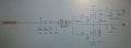
The permanent DC motar is connected to as per below schematic.
Now i am not able to understand the circuit flow. How is the motor working.?
Gate driver IC:
https://www.infineon.com/dgdl/Infin...N.pdf?fileId=db3a30433e30e4bf013e3c649ffd6c8b
Schematic :

Regards,
Could anybody let me understand the working of below circuit.?
I am totaly blank to understand.
The permanent DC motar is connected to as per below schematic.
Now i am not able to understand the circuit flow. How is the motor working.?
Gate driver IC:
https://www.infineon.com/dgdl/Infin...N.pdf?fileId=db3a30433e30e4bf013e3c649ffd6c8b
Schematic :
Regards,