The book says the definition of H para , my question why V1 and I2 set on the left of equation not V2 , I1 on the left of equations
and the def of Transmission para , why the minus is used in the equation not the plus sign? thank you all
IIRC, all of the basic parameter definitions {z, y, h, and g} have one input and one output quantity on each side.
For the transmission parameters, I think the negative sign on I2 stems from the current on one side must be the negative of the current on the other. But, again IIRC, some authors don't define it this way.
so, the H parameter , I set V2, I1 in the left side is also correct? and in Transmission para I set plus sign instead of minus is also correct? they give the same result , right???
so, the H parameter , I set V2, I1 in the left side is also correct? and in Transmission para I set plus sign instead of minus is also correct? they give the same result , right???
You can't just go changing them however you want and expect to get the same result.
Look at the subscripts.
On the left, you need something from the input on the top and something from the output on the bottom.
On the right, you will get something from the input on the top and something from the output on the bottom.
As for the transmission parameters, you need to use them as they are defined and be consistent. If you use a text that defines them differently, then the definitions are different and you need to use them according to those definition.
Transmission parameters usually do not have subscripts because they do not follow the subscript convention. This is why they are usually called ABCD parameters.
For example: the left side of original equations of Hybrid para is V1 and I2 , now if I change into V2 and I1 then the result is the same with original equation????
For example: the left side of original equations of Hybrid para is V1 and I2 , now if I change into V2 and I1 then the result is the same with original equation????
The values of the parameters are based on which quantities are used. You can't just use an input where an output was and expect to get the same results.
Think about a very simple case of a network where the output voltage is 1/10 of the input voltage. Do you really think that it makes sense that you can swap input and output and all of a sudden have the input voltage be 1/10 of the output voltage?
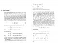
The book says the definition of H para View attachment 337639, my question why V1 and I2 set on the left of equation not V2 , I1 on the left of equations
and the def of Transmission para View attachment 337641, why the minus is used in the equation not the plus sign? thank you all
To start with the h-parameters, take a T network made with three resistors and do a circuit analysis keeping in mind that you want to define the following parameters:
1. Short-circuit input impedance.
2. Short-circuit current gain.
3. Open-circuit reverse voltage.
4. Open-circuit output admittance.
Oh and I1 and I2 both point into the network.
When you define these parameters so that you can do measurements on that T network (or any other two port network) you end up with the equations you have shown with the h-parameters.
You don't have to use these, there are other types. For example:
1. Admittance parameters
2. Impedance parameters
You can make your own by converting them, then you'll end up with different parameters. Then you'll have to correlate that to physical measurements you make on the network like those four outlined above. If you can't then they will be worthless I think. You might end up with some sort of inverse parameters that can be equated to the h-parameters.
You could try making I1 and I2 point differently I guess and see what you end up with.
I understand the reason for your question though, I think it is because we normally want to calculate the output from the input conditions, while V1 on the left seems to contradict that basic intuition.
However, if you want to put V2 on the left, then you'd have to define a constant equal to:
hxx=h11/h12
and now I think it might be hard to relate that to a direct physical measurement that is relatively easy to make and maybe understandable. We'd have to call it something, and it seems like it would have to be called the short circuit input impedance over the open circuit reverse voltage, which would be 1/amperes which I don't think we have a unit for (maybe somewhere). "Short-circuit-input-impedance-open-circuit-reverse-voltage reciprocal-of-current?". Have fun measuring that
Thus, the forms of the two equations may be written that way so that we can make the required measurements in real life without too much trouble, and then calculate everything, while keeping the forms in a neat and orderly manner. Remember you can always just solve for V2 given those equations.
Another aspect is that network equations are hardly every used alone so they would be mixed with other equations anyway. Keeping the forms as simple as they are is probably the best way.
See what you can come up with and see if you can find a reason to do it another way, other than the other well-known ways of doing this.
Can you please simplify what you mean or visually compare to something easy to understand about H para? about Transmissions parameter I understand why they normally use the minuss sign because the output often is considerd to go out the circuit.
Can you please simplify what you mean or visually compare to something easy to understand about H para? about Transmissions parameter I understand why they normally use the minuss sign because the output often is considerd to go out the circuit.
Yes I can understand the minus sign, that must be right. The h params are always into the network.
Ok I'll see if I can get an example together but probably will have to be tomorrow sometime it's late here now.
It's all about keeping things simple. You want to express things as simple as you can yet still get the meaning across, and you want to be able to relate that to something you can use in practice that is not exceptionally difficult to perform. If the parameters are not easy to measure, you end up trying to measure things that are more difficult, and then expressing them in some math form may end up being difficult or too abstract. You also want to present it in a general way so that you can use it in many instances that could be much more complicated.
The main idea here is that if you put V1 on the left instead of on the right, you can convey the information in a simpler way, and also make measurements on a network more straightforward, and it's simpler to write down and convey to other people interested in using the technique.
Things have changed a bit though too over longer periods of time. Back around the early 1950's when H params started to be used, there were no personal computers and other computers were far and few, so engineers were probably still using slide rules. They wanted everything simple. Even a simple division added time to the calculation. Today we use spice, which almost anyone can use, so we can easily put up with more complicated models of transistors and things like that.
Measurements on actual components is simpler today too, but it still takes time and effort to get it all right. The simpler the measurements, the more likely they will be correct.
So it's not just about the math itself, but the application of that math, and the measurement difficulty and overall usage of the techniques.
This is a little more esoteric because it's not just about the math it's about the understanding of the entire concept and why it happens to be done that way. It may seem arbitrary at first, but it's fairly well thought out.
Can you please simplify what you mean or visually compare to something easy to understand about H para? about Transmissions parameter I understand why they normally use the minuss sign because the output often is considerd to go out the circuit.
I think this can explain it better than I can. They talk about transistors but it really can be used for any two port network. They also talk about how one of the Z parameters could be harder to measure than the H parameters. This is an excerpt from an engineering circuit analysis book by Hayt and Kemmerly, et al. It's too bad they are both deceased now.
The book says the definition of H para View attachment 337639, my question why V1 and I2 set on the left of equation not V2 , I1 on the left of equations
and the def of Transmission para View attachment 337641, why the minus is used in the equation not the plus sign? thank you all
Can you please simplify what you mean or visually compare to something easy to understand about H para? about Transmissions parameter I understand why they normally use the minuss sign because the output often is considerd to go out the circuit.
I realized that I forgot to mention one important point regarding your question.
That is, a two port network does not need to have its ports labeled as "input" and "output" the way we normally perceive a circuit diagram reading left to right. It's actually a "two port network" because in the most general sense the input and output are not always defined by reading from left to right, which would normally put the input on the left and the output on the right.
The more correct interpretation of a two port network is that BOTH of the ports are BOTH input and output at the same time, meaning they are kind of like any other circuit element such as a resistor, which really does not have a well-defined input or output until we declare it to be as such. For the usual amplifier circuits we talk about a lot in forums like this, the input and output are usually well defined in that the input is usually on the left and the output is on the right. When we get into magnetic circuits though we find that the left side can take on both input and output functions in the same circuit, and so can the right side. A simple example would be a transformer, which can have power flow in both directions, and where the input impedance affects the output impedance and in turn the output impedance affects the input impedance. When we place it into some application the left side and right side usually take on the particular roles of input and output, but not always. It acts just like another general purpose circuit element.
All of this would make the node labels (V1, V2, I1, I2) look more arbitrary rather than some hard and fast rule that must be followed for every circuit. You can see then why V1 and V2 are not as important to be deemed as input and output, but just as general voltages, and that makes it less important which ones we refer to as input or output until the final circuit application comes about.
There is another interesting aspect of a two port network as an amplifier such as a microphone amplifier.
Considering it to be a two port network, that means it has the usual forward transfer function, but also a reverse transfer function. We usually ignore the reverse transfer function but we can't always do that. That means that if you inject a signal on the output you get some signal on the input, even though it is not very high in amplitude in most cases. That lower level signal makes it look like it's not a two port network so we often ignore that reverse characteristic. When it comes to input and output impedance calculations though, it may be important. We still don't always need that though.
Another two port network is, of course, the transistor. The bipolar transistor, for one, has both a forward Beta and a reverse Beta, which means again a signal on the output can produce a small signal on the input. Spice considers this to be important enough to include it in most models. This kind of device might be where the idea of Hybrid parameters came about in the past.
 Facebook
 Google
 GitHub
 Linkedin


")