H bridge problem

Thread Starter

rdemirci

Joined Aug 28, 2015
6
Hello,

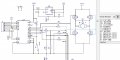
I have an h-bridge to drive a DC motor. DC motor is used as a lock for a box. The main purpose is to rotate the motor in one direction for 50ms to open the lock, stop the motor and wait 50ms and rotate reverse direction for 50ms to close the lock and stop the motor again. This sequence is done sequentially everytime a request is done.

Sometimes when I request this sequence, the motor stucks to rotate forever in one direction and never stops. I could not understand what is going wrong? Could you please help?

Attached is the schematic.

Regards,
Rifat
 

Attachments

MikeML

Joined Oct 2, 2009
5,444
Does the processor hang when this happens (you have to reset it to clear it)?

That is a horrible H-Bridge. Where is the shoot through protection?

You likely have a ground-loop between the H-Bridge and processor.
 
Last edited:

Thread Starter

rdemirci

Joined Aug 28, 2015
6
Hello Mike,

No, the processor does not hang when this happens.

The transistors used at the h-bridge are dmg1012uw and behave like attached.

Regards,
Rifat
 

Attachments

grahamed

Joined Jul 23, 2012
100
Diagram shows both N and P devices.

Why is it a horrible diagram? Be specific.

What is shoot-through? If you mean fly-back or back emf or any of the other well-established terms....a diode is shown on the FET equivalent.

Of course he has a ground loop. How on earth would an h-bridge work without one?

OP have you measured the gate voltages when the circuit is free running? Assuming that the physical circuit matches the schematic (always a dangerous assumption that) then two FETs are are on when they shouldn't be.

Either the FETs are being turned on when you don't expect (most likely the program is wrong) or the FETs are latching up somehow.

Latch-up can be caused by excess or reverse voltages - possibly the motor acting as generator for a brief instant when the FETs switch off, however you seem to have reverse diodes in the FETs which should prevent this.

When the processor turns the FETs off does it pull the lines low/high or does it just leave the lines floating? This would be bad practice - it would leave the gate capacitance charged.
 

Thread Starter

rdemirci

Joined Aug 28, 2015
6
Hi grahamed,

I have not measured the gate voltages, but I will do that. I have checked the physical circuit and the schematic, unfortunately they are same. So as you said two FETs are on when they shouldn't be.

As I see this wrong behaviour not always, and rest it behaves correct, I do not think that the program is wrong.

I tried both to drive control lines LOW,LOW and HIGH,HIGH, but nothing changes. So the FETs are latching up I think as you said but why?

Regards,
Rifat
 

Marcus2012

Joined Feb 22, 2015
425
Diagram shows both N and P devices.

Why is it a horrible diagram? Be specific.

What is shoot-through? If you mean fly-back or back emf or any of the other well-established terms....a diode is shown on the FET equivalent.

Of course he has a ground loop. How on earth would an h-bridge work without one?

OP have you measured the gate voltages when the circuit is free running? Assuming that the physical circuit matches the schematic (always a dangerous assumption that) then two FETs are are on when they shouldn't be.

Either the FETs are being turned on when you don't expect (most likely the program is wrong) or the FETs are latching up somehow.

Latch-up can be caused by excess or reverse voltages - possibly the motor acting as generator for a brief instant when the FETs switch off, however you seem to have reverse diodes in the FETs which should prevent this.

When the processor turns the FETs off does it pull the lines low/high or does it just leave the lines floating? This would be bad practice - it would leave the gate capacitance charged.

Thanks I couldn't make out those little arrows lol, my terrible eyes :)

  • Shoot-through - cross conduction:
If the control signals to two opposing MOSFETs overlap, a situation can occur where both MOSFETs are switched on together. This effectively short-circuits the supply and is known as a shoot-through condition. If this occurs, the supply decoupling capacitor is discharged rapidly through both devices every time a switching transition occurs. This results in very short but incredibly intense current pulses through both switching devices.
The chances of shoot-through occurring are minimised by allowing a dead time between switching transitions, during which neither MOSFET is turned on. This allows time for one device to turn off before the opposite device is turned on.

The MOSFET
 

grahamed

Joined Jul 23, 2012
100
Hi Rifat

You mean you have tied the gates to the rail/ground after the circuit has started to run on? If you tie the gate of a FET to its source it must turn off unless it is latched-up.

Often latch-up destroys the device bit not always.

You could try new FETs and connect a backwards diode across each one. Maybe the one shown in the FET-diagram is not actually there - a resistance meter would find it.
 

grahamed

Joined Jul 23, 2012
100
Hi again

Try adding 100k across each GS. When the circuit free runs remove the gate-processor connections - if it carries on you will know it is not the processor and I mean the processor not the program. Maybe the switching is upsetting the supply rail and hence the processor and hence the program.
 

Thread Starter

rdemirci

Joined Aug 28, 2015
6
Thank all for the answers.

The control lines are drived by an i2c port extender. I send the control byte via i2c and it is driven from the parallel output of the IC. The procedure I do is as follows:
- drive "10" for 50ms to turn motor right
- drive "11" for 50ms to stop motor
- drive "01" for 50ms to turn motor left
- drive "11" to stop motor.
As you can see I have stop delays between turning motor left and right. So I do not think that the software causes a wrong behaviour to the circuit.

When it stucks I turn power off/on and try again, then it works fine. So I do not think that FETs are destroyed.

I suspect from the switching characteristic of the transistors bur 50ms of time should be enough for it.

Switching may effect the IC. For it I have to isolate that side by using optocouplers but I leave it for the last chance.

Maxheadroom, tou mean driving "00" then "11" to stop the motor, is that correct?
 

grahamed

Joined Jul 23, 2012
100
Braking.

Setting the two gate drives the same, i.e. upper or lower pair on and the other off, is the standard way to cut-off motor drive.

If gate drives are such as to turn on upper pair, how can they not turn off lower pair? and vice-versa.

ASAIK (in my current befuddled state) the only way to prevent braking is to leave the motor open-circuit, and this h-bridge (with back diodes) can't do that. Maybe with 4 gate drives.....
 

grahamed

Joined Jul 23, 2012
100
Try replacing motor with a back-to-back LEDs and series resistor - much less current draw, won't affect rail. See what happens. What is motor current draw? Is regulator up to job?
 

Thread Starter

rdemirci

Joined Aug 28, 2015
6
Grahamed, I will try it. But just to give an info; the motor is driven by 3.3 V and 125mA current draw.

By the way, can driving 5V from the gate cause a problem?
 
Top