I'm pleased with the way the circuit is working to produce an AC square wave to the poles of the transformer. If I use a resistor instead of an inductor, it all looks fine.
Now I'm ready to simulate a wall-wart, but I'm at a loss on what to use in LTSpice. The educational examples don't seem to apply, but that could be because I don't understand what I'm seeing.
I think further simulation using a good wall-wart model would be worth the effort. But if the results could be misleading, would I be better off to just proceed to testing?
You've missed the context. I'm using a wall-wart transformer in reverse, applying a 12V square wave to get AC out. I have no idea how to simulate that in LTSpice, beyond comments I found here, post 13:
"To model wall wart in spice use a transformer to obtain the open circuit
step down ratio, and a series resisitnace in the secondary that provides
a current limiting by dropping on the output side. Fast and coherent!
marco"
Any idea what inductance values might be typical for a 120V to 12V power transformer?
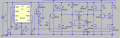
This is my updated schematic. It does a nice job of switching the MOSFET gates and appears to be giving good pulses to the load. I've simulated EL tape as C6 with a series resistance of 10K. Wild guess. R8 was needed to stabilize the simulation.
I want to use the correct model for the IRF540N MOSFETs that I have. I downloaded the .spi file from IR. I followed the procedure described here, but it's not working. The ".lib" or ".inc" commands seem OK, they don't generate an error.
How do I add the IRF540N to the database of MOSFETs in LT Spice?
This is how I do it because I hate the include stuff.
Make a new folder (lets call it new) for your new parts. Make a "new" in both the spice sub and sym folders.
Get the sub circuit model from IR and save it in the sub new as IRF540N.sub - The . sub after the name is important. It will be saved as a text file, but it's name is IR540N.sub
Next explore to the spice/lib sym file. Find the nmos model from the list and open it. You may need to tell it to open it with spice if it just opens a text file. You should now have the symbol on the screen. Go above to the menu and click edit and attributes. This should open another little window.
Change the prefix to X. Add the path to the sub circuit by putting in new/IRF540N.sub Add IRF540N to value 1 and 2. Add what you like to description. Click file save as IRF540N. Now when you want to add a IRF540 to a schematic, new will be in the main parts menu - just click it and you will see all your new parts. Click on the one you want and insert it in the schematic and your done. A word of warning. This may not be the correct way to do it but it works for me and it saves typing the include statement every time.
Good luck!
Perfect. I was this close. (Fingers held together.) But a miss is as good as a mile and your tips got me across the finish line. I think. Now the simulation runs and the .sub or .inc crud is gone.
I was hoping I would be able to see the properties of the added part, as you can with the built-in IRF530 for instance. Does it make sense that I cannot?
The Mac version (LTspice IV) is slightly different. Here's the procedure I used. Note that I didn't bother to use the "new" folders, and just added my new part to the existing directories.
0. Quit LTspice if it's running. Changes to the sub and .asy files don't appear to take effect until you restart the program.
1. Download the irf540n.spi file from IR, either by itself or find it in the big package they present for download.
2. Find and rename the file by changing the extension to .sub. It's a text file and you can open it if you like. But there's no need to alter it.
3. Put the file in your User:Library:Application Support:LTspice:lib:sym folder. (In Finder, hold down the option key and select Go --> Library from the menu to open that folder.)
4. Put an identical copy of IRF540N.sub into the User:Library:Application Support:LTspice:lib:sub folder.
5. Create a new .asy file. Back in the sym folder, find the symbol file that is appropriate for the new component, in this case it was nmos.asy. Duplicate it and rename it as you like, e.g. to IRF540N.asy. Or you can open it in LTspice and do a "save as". Open the new .asy file in LTspice. You should see a drawing of the symbol, not a text file.
6. Right click in the document and select View:Attribute table
7. Change the Prefix to X and change the SpiceModel to IRF540N.sub and click the X to turn off the visibility of that field.
8. Set the Value field to IRF540N. If I also set Value2, then I had to click off the visibility.
9. Change the Description field as you like.
10. Restart LTspice.
11. You should be able to choose IRF540N from the same symbol menu list where you see res, cap, nmos, etc.
No, but I'm giving up for the night. If your guesstimates for the wall wart inductances are reasonable, then I'm not sure this is going to work. I can't seem to get the current I need across the capacitive load of the EL. But in the simulation, that current is very sensitive to the series resistance of the capacitor, and I have no idea what the real value ought to be. I tend to think it would work but I'm not sure how efficient it would be.
I'm wondering if using a square wave is not so efficient. I could use PWM to simulate a sine wave (assuming I could learn to use a micro) but I'm not sure how to do that either, since I believe I'd need to low-pass-filter the PWM before it hits the transformer. Since I need about 1A there, that's quite a filter. Another option would be to use a DC-DC boost to create a ~200VDC rail, and then H-bridge that directly to the EL tape. No transformer. Hmmm.
Brain shutting down.
The latest: (requires IRF540N.sub file in your lib:sym and lib:sub folders, and a IRF540N.asy file in your sym folder.) View attachment My inverter3.asc
That more-or-less fits with other sources I found, although it was difficult to find much information on these small power transformers.
I have two big old wall wart transformers I'm looking at for this project, both nominal 120VAC-12VAC. First is rated to 1A on the secondary, the second one to 830mA. The second one also shows "max 14V at 500mA".
Open circuit voltages: 12.70, 12.45 volts
Primary DC resistance: 44.8, 97.0 Ω
Secondary DC resistance: 0.7, 2.2 Ω
 Facebook
 Google
 GitHub
 Linkedin
")