Hello!
I am making a guitar pedal which will allow me to blend a clean guitar signal with a distorted/dirty signal from some other pedal.
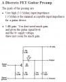
This is the circuit I came up with:

CIRCUIT DESCRIPTION:
The pedal has 4 signal connectors:
IN - inbound clean signal from guitar
SEND - outbound clean signal which goes to another pedal
RETURN - inbound distorted signal from the other pedal
OUT - combination of distorted and clean signals
The circuit has 3 main sections:
Input section, based around O1
Clean signal mixer section based around O2 and VR1
Dirtiy signal mixer section based around O3 and VR2
Main components:
O1 - unity gain preamp. Makes sure the signal doesn't drop when split between O2 and SEND
VR1 - clean blend potentiometer. Controls the amount of clean signal
O2 - unity gain - sends the desired level of clean signal to output
VR2 - dirty blend potentiomenter. Controls the amount of distorted signal from the other pedal
O3 - unity gain - sends the desired level of dirty signal to output
Other components:
C1, C2, C3, C4 - DC decoupling caps
R3, R6, R9 - biasing resistors which keep the opamps non-inverting inputs near GND level
TRIM1, TRIM2, TRIM3 - trimmers which allow me to fine-tune the gain of each opamp
R8 - raises the input impedance of RETURN input. 10k of VR2 doesn't seem enough when compared to other similar circuits on the net.
R5 - basically a copy of R8. Probably not needed here, but it doesn't hurt.
R4 - protection in case 'SEND' connector is shorted
R7, R10 - prevents the output from O2 to leak out through output of O3 and vice versa
SPDT1 - bypass switch
SW1 - power on/off switch
9V - currently 9v battery, later a standard 9V wall adapter
I built the circuit on breadboard and it's working surprisingly good but I have a few questions before I build it on a PCB:
QUESTIONS:
1.) Schematic has no noise reduction caps yet. Are there any obvious places where you would put them and at what value?
When testing on breadboard, the circuit has a standard 50Hz hum, but based on my previous projects, it will be reduced once I make a PCB and enclose it in a metal box.
Other noise problem which I noticed is that when VR1 or VR2 pots are near the middle position, there is a high pitched hiss.
When pots are either fully "on" or fully "off", the hiss is gone.
Do you have an idea where this noise might be comming from?
2.) Should I add another Opamp in front of SEND, so that signal level which goes to O2 doesn't get affected by input impedance of the other pedal?
I tested it with two other pedals, and I didn't notice any problems, but if there is some 'best practice', I'd like to learn.
This is a hobby/learning project, so I don't expect anyone to spend any serious amount of time on answering this.
I'm just looking for input from someone more experienced, so I can avoid any obvious beginner mistakes.
Thank you!
I am making a guitar pedal which will allow me to blend a clean guitar signal with a distorted/dirty signal from some other pedal.
This is the circuit I came up with:
CIRCUIT DESCRIPTION:
The pedal has 4 signal connectors:
IN - inbound clean signal from guitar
SEND - outbound clean signal which goes to another pedal
RETURN - inbound distorted signal from the other pedal
OUT - combination of distorted and clean signals
The circuit has 3 main sections:
Input section, based around O1
Clean signal mixer section based around O2 and VR1
Dirtiy signal mixer section based around O3 and VR2
Main components:
O1 - unity gain preamp. Makes sure the signal doesn't drop when split between O2 and SEND
VR1 - clean blend potentiometer. Controls the amount of clean signal
O2 - unity gain - sends the desired level of clean signal to output
VR2 - dirty blend potentiomenter. Controls the amount of distorted signal from the other pedal
O3 - unity gain - sends the desired level of dirty signal to output
Other components:
C1, C2, C3, C4 - DC decoupling caps
R3, R6, R9 - biasing resistors which keep the opamps non-inverting inputs near GND level
TRIM1, TRIM2, TRIM3 - trimmers which allow me to fine-tune the gain of each opamp
R8 - raises the input impedance of RETURN input. 10k of VR2 doesn't seem enough when compared to other similar circuits on the net.
R5 - basically a copy of R8. Probably not needed here, but it doesn't hurt.
R4 - protection in case 'SEND' connector is shorted
R7, R10 - prevents the output from O2 to leak out through output of O3 and vice versa
SPDT1 - bypass switch
SW1 - power on/off switch
9V - currently 9v battery, later a standard 9V wall adapter
I built the circuit on breadboard and it's working surprisingly good but I have a few questions before I build it on a PCB:
QUESTIONS:
1.) Schematic has no noise reduction caps yet. Are there any obvious places where you would put them and at what value?
When testing on breadboard, the circuit has a standard 50Hz hum, but based on my previous projects, it will be reduced once I make a PCB and enclose it in a metal box.
Other noise problem which I noticed is that when VR1 or VR2 pots are near the middle position, there is a high pitched hiss.
When pots are either fully "on" or fully "off", the hiss is gone.
Do you have an idea where this noise might be comming from?
2.) Should I add another Opamp in front of SEND, so that signal level which goes to O2 doesn't get affected by input impedance of the other pedal?
I tested it with two other pedals, and I didn't notice any problems, but if there is some 'best practice', I'd like to learn.
This is a hobby/learning project, so I don't expect anyone to spend any serious amount of time on answering this.
I'm just looking for input from someone more experienced, so I can avoid any obvious beginner mistakes.
Thank you!