Guitar effect on stripboard, tips for ignorants

Thread Starter

Zoso

Joined Jul 10, 2022
2
Hello everyone,
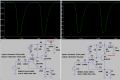
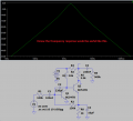
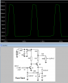
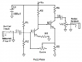
I am new to the forum. I am not an electronics guy, but as an engineer, and a fairly manual person, I think I will be able to juggle enough. I want to build a guitar pedal from scratch (starting from "easy level"), to help me I used a graphic app on which to convert the diagram you see:
IMG_20220710_154439~2.jpg
I think I didn't make any mistakes, please correct me if you notice something wrong. Getting to this point I couldn't figure out how to properly close a circuit and if it is possible to do it in true bypass mode with a 6-pin switch. For many of you this will be trivial, so could you please help me out? Another question: of the two pins of the input and output jacks, will I connect only one or should I connect the other one to ground? I don't know, I'm a little confused about how to handle those 4 outgoing wires.
I'll start this way, in the meantime thank you for any tips.
 

MrChips

Joined Oct 2, 2009
30,714
Welcome to AAC!

The circuit schematic does not look correct. Why was the output capacitor taking the signal from close to 9VDC rather than the collector of the output transistor.

I would suggest that you test the circuit first on a solderless breadboard to see if it meets your requirements.
 

Thread Starter

Zoso

Joined Jul 10, 2022
2
Hi MrChips,
I trivially got the pattern from the internet without asking myself excessive questions about its correctness; I am still in the learning stage. Are you talking about the 3rd? How come you say so?

Yes, trying it on a breadboard was my intention.
 

MrChips

Joined Oct 2, 2009
30,714
A basic guitar fuzz pedal circuit is simple: amplify the signal like crazy and then clip it to produce square waves.
Two diodes wired in parallel in opposite polarity will clip sine waves into square waves. The goal is to create a lot of distortion.

1657510523449.png
 

Ian0

Joined Aug 7, 2020
9,671
@boostbuck @MrChips: That’s pretty much a standard Fuzzface, modified for silicon transistors.
Because it was originally germanium, ground would have been +9V.
The connection of the output signal is because the signal on the collector of the second transistor is a 9V p/p squarewave, and the signal required at the input of a guitar amplifier is about 30mV, so lots of attenuation is required.
 

Audioguru again

Joined Oct 21, 2019
6,674
Any overdriven amplifier produces symmetrical clipping distortion. Two back-to-back diodes also produce symmetrical distortion.
Symmetrical distortion has odd-numbered-harmonics.
A Fuzz Face circuit produces odd-numbered-harmonics, additional asymmetry with even-numbered-harmonics plus a messed-up frequency response.

There is a Heineken beer ad on TV where the electric geetar sounds awful like a buzzer.
 

Attachments

Ian0

Joined Aug 7, 2020
9,671
I corrected the frequency response of the Fuzz box circuit in post #1 so that it plays more than only 2kHz:
Where did you get R1 from? It doesn’t appear on the TS’s circuit nor on the original.
The response depends hugely on the source impedance, which is somewhere in the realms of 6kΩ+6H. It normally has a very low input impedance which turns the pickup impedance into a low-pass filter which tends to remove the harmonics, so that the output trapezium-wave is at the fundamental frequency only.
 

Audioguru again

Joined Oct 21, 2019
6,674
My 100k input resistance is an assumed impedance of a magnetic guitar pickup. Without it the gain is way too high and the output of the circuit has clipping with an input of only 0.2mV peak.

I found another Fuzz Face circuit that does not have the frequency response messing-up capacitors:
 

Attachments

Ian0

Joined Aug 7, 2020
9,671
My 100k input resistance is an assumed impedance of a magnetic guitar pickup. Without it the gain is way too high and the output of the circuit has clipping with an input of only 0.2mV peak.
Use 6kΩ+6H and you won’t be far wrong. They vary a bit but that value is easy to remember.
I found another Fuzz Face circuit that does not have the frequency response messing-up capacitors:
If it was on a silicon version, then it was probably put there to make it more germanium-y.
 

LowQCab

Joined Nov 6, 2012
4,026
It's supposed to be a really bad design,
just like any of the Tube-Amps or Speakers it's designed to drive.
"Improving" the Frequency-Response is going backwards.
But it should probably be centered around 1K instead of 2K for the best sound.
.
.
.
 
Top