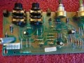
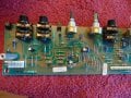
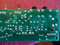
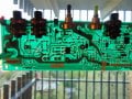
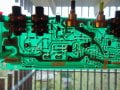
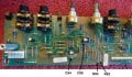
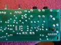
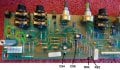
Ok. I have a better take on the circuit and schematics.
Ignore the annotations I have made in post #75. As far as I can see, the schematics are correct.
What they label as +V and -V is the same as +16V and -16V.
What I cannot locate are C52 and C53, 100μF 35v.
I also cannot locate R82 and R83, 47Ω.
What is the value written on the two black capacitors I have labeled as C54 and C55?
These should be 47μF 35V.
I would get two 47Ω ½W resistors and two 100μ 35V aluminum electrolytic capacitors just in case we need to install these "missing" components.
(I have to double check that those two jumpers I have indicated can be replaced with R82 and R83.)
(Note that you do not need to install the upper board, the equalizer connection, or Q4, the transistor already removed to make this test.)
Those 2 caps that you point to are both 100uf 35v. When I looked at the schematic (page 3
bottom right), I wonder where C52 & C53 are also, could these be those instead of 54 and 55?
Just like at the transformer I thought I saw on the schematic mentioning 2 different ones.
Could the maker of this be showing two different models of amps, using the same schematic and
the tech would somehow know it? Plus... I am almost certain that I replaced these with the
same that was there.
There is something strange with IC6.
According to the bottom view photo it would appear that there is a trace connecting pin-1 to pin-5.
Can you verify this?
It is conceivable that revisions were made at some point and the PCB does not match the schematic.
I would be inclined to leave C54 and C55 as 100μF (just to save the trouble of having to change them).
I would replace those two wire jumpers with R82 and R83, 47Ω ½W resistors.
I would drill holes into the PCB and mount two additional capacitors C52, C53 100μ 35V across the zener diodes D22 as per the schematics. Watch the polarity of the electrolytic capacitors.
I would cut the trace between pin-1 and pin-5 at IC6 (assuming that this connects pin-1 to pin-5). You can always reconnect the pins later.
Looking at the power section drawing again there are two C51's (page 3 bottom mid-right). I think my theory may have some weight to it. This schematic may show two amps.
Looking at the power section drawing again there are two C51's (page 3 bottom mid-right). I think my theory may have some weight to it. This schematic may show two amps.
I see the two C51, 0.047μF. These are for RF filtering.
These have nothing to do with two amps. This could be typo error. There is nothing unusual about showing two capacitors such as these in the same schematic. This is drawn this way for various reasons.
We are still missing major RC filter components in the low voltage power supply as per the schematics. It is possible that someone revised the PCB and eliminated these components. I would be inclined to restore them. They do make sense as a way of reducing AC mains hum.
Okay. I found this also and it shows system block diagram. So what do you think I should try? Not sure I have the parts today, but I will look into it tomorrow.
Just been out on a bike ride to clear my mind and I thought of this.
Here is my take on what has happened (purely speculation).
(btw, the previous incarnation of the Crate KX-160 was K160XL.)
Your amp has an older version of the PCB.
The schematic has been revised since then to tackle the very same issue you are having, that is, hum in the output. The low voltage power supply ±15V in the revised schematic has additional RC filtering to help reduce the power supply ripple.
What we need to do firstly is to clarify the confusion between IC5 and IC6.
Edit: solved, I can see IC 6 now. (Can you post similar photos of the rest of the bottom board? Your last batch of photos great, good enough for me to trace the circuit.)
This is what I would do.
Install C52 and C53, 100μF 35V aluminum electrolytic capacitors (radial package) where I have drawn two green "circular" shapes. Observe the polarity of the capacitors.
You will have to drill holes and scrap away at the photo resist on the solder side in order to solder the capacitor leads.
Remove those two wire jumpers and replace with R82, R83, 47Ω ½W.
Reinstall Q4. Make sure you get the orientation correct.
There is not a Radioshack in Denver that has the resistors. They have been having store-wide sales and several locations are closing (including the one near me). A sad Memorial Day indeed. I did on a positive note have the 2 caps and have them in.
There is not a Radioshack in Denver that has the resistors. They have been having store-wide sales and several locations are closing (including the one near me). A sad Memorial Day indeed. I did on a positive note have the 2 caps and have them in.
BTW, if you are going to make a special trip or place an order for components, you might as well get some 8-pin DIP sockets and NE5532P or NE5532AP chips. You may want to replace IC6, RC4558, with a low noise opamp such as NE5532 or TL072.
Maybe but no one is answering today. I will see what they say tomorrow. Many places like that either won't sell direct to the public or they want you to buy a certain amount. Regardless, thanks for the name; I will call them. BTW, since there are only 2 of those RC4558 why not change both. I did not know you could change them to the NE5532P and that they would be lower noise but work the same.

 Facebook
 Google
 GitHub
 Linkedin