Guitar Amp w Cement Resistors Loud Pops & Noise

Thread Starter

ColoradoRobert

Joined Jan 22, 2016
155
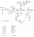
Pin 3 on IC 1 has .62mv, Pin 1 has 0v. So if I am looking at the schematic right IC 1 = the first 4 legs go to channel 3
and the other side of IC 1 (legs 5-8) go to channel 1. I had the generator sending 100mv at 1khz into channel 3 input jack (no sound).
 

JoeJester

Joined Apr 26, 2005
4,390
Turn up the gain for input 3. See if the output (pin 1) changes.

One feature of your meter is you can measure the frequency. You could put your meter to that function and ensure you are looking at the 1000 Hz tone.

Did you adjust the input voltage to 35.35 mV?
 

Thread Starter

ColoradoRobert

Joined Jan 22, 2016
155
I set the input voltage according to what the schematic says 100mv @ 1khz. Turning up the gain to max pin 1 barely reads mv in dc. Zero on volts ac or dc.
 
Last edited:

JoeJester

Joined Apr 26, 2005
4,390
The schematic says 100 mV p-p. Your meter reads rms. 100 mV p-p = 35.35 mV rms. The boldfaced voltages are rms in my previous post..

You can repeat this test on channel 1 and you should have good results.
 

Thread Starter

ColoradoRobert

Joined Jan 22, 2016
155
This is really screwy. When I touch pin 5 with the red meter lead (but not common to ground) I get close to 30mv but when I common to ground it drops even though sound is coming through the speaker plugged into channel 1 (10db input). Pin 7 does not go up to the right amount either.
 

JoeJester

Joined Apr 26, 2005
4,390
On an earlier post I mentioned I replaced all the chips with NE5532P but maybe that RC4558 should go back into this spot.
Inspect that portion of the NE5532P associated with Channel 3. The underside, and inspect for poor soldering joints, solder bridges, etc. If you post a picture of that area, I'll look at it too.
 

JoeJester

Joined Apr 26, 2005
4,390
all your readings are with respect to ground.

These readings are normally done with an oscilloscope.

Measure the DC voltages around the Chan1 (or chan 4) and then around chan 3.

Lets see if there are discrepancies, if you didn't find any visual problems.
 

JoeJester

Joined Apr 26, 2005
4,390
I get close to 30mv but when I common to ground it drops even though sound is coming through the speaker plugged into channel 1 (10db input). Pin 7 does not go up to the right amount either.
Drops to what?

What about the output pin? when the gain is at 0 and at max.

Where are you placing the black probe (ground)?
 
Last edited:

Thread Starter

ColoradoRobert

Joined Jan 22, 2016
155
Hopefully Joe, I can get back to this later this morning and do better checking with this meter. In the meantime
I snapped a pic of the spec booklet for this meter. Small paged booklet but I think this is the page you want. DSC02429.JPG
 

JoeJester

Joined Apr 26, 2005
4,390
That pic covered AC and DC. You can use the 6 volt range for all your AC readings. 1 kHz is the high end of your frequency response, so that signal may appear lower than it should. We might be moving the frequency to another one and recomputing the values expected.

Your meter also measures frequency, capacitance, and temperature. You might want to review those specifications as well. I wish I could find a user manual online.
 

Thread Starter

ColoradoRobert

Joined Jan 22, 2016
155
With channel 1 receiving tone pin 5 reads 8.02 acmv, pin 7 reads 34.12acmv

With channel 3 receiving tone pin 1 and pin 3 both read 0.39 acmv gain full up.
Turn gain all the way down pin 3 about the same 0.38/39 pin 1 read 0.37acmv

Pin 4 16.54 vdc. Pin 8 15.79 vdc. The greatest problem I am having since the board is not numbered is figuring out what belongs with channel 3 and then knowing what to expect as far as voltages. I went ahead and swapped out the NE55 back to a new RC. Same results
= tone through everything but channel 3.
 
Last edited:

Thread Starter

ColoradoRobert

Joined Jan 22, 2016
155
The Tougs meter that you found and I bought, is auto-ranging. I don't think it has a way to manually set the scale.
Pin 1 2.62dcmv - Pin 2 2.84dcmv and dropping - Pin 3 1.91dcmv. I suppose I could just start unsoldering diodes and caps and put them on my cheap tester to see how they look and go from there unless you have a better idea. Problem is there are almost 100 components on this little top board.
 
Last edited:

Thread Starter

ColoradoRobert

Joined Jan 22, 2016
155
Is there something that can remove that glue caulking? If I remove a few things I'd like to clean the board off from that left over glue or caulking.
 

JoeJester

Joined Apr 26, 2005
4,390
You have a function button on that meter. Like I said, I wish I could find that manual to see what it is telling you, but the display has an auto and manual indicator. Read the manual.

Your meter tests diodes and capacitance. You only need to remove one lead to ensure it's not in the circuit to test it. How many pages is that manual? If you think it would be worth it, take a picture of every page in english.

Problem is there are almost 100 components on this little top board.
You are ONLY testing the few components associated with channel 3.

channel3.png

Do you have a capacitor handy? Something between 0.1 uF and 1 uF? We can use one to block DC when making the AC measurements.
 

Thread Starter

ColoradoRobert

Joined Jan 22, 2016
155
Scanned Meter Manual - even though on page 8 it talks about a range button so you can go from manual to auto; this Model M102 does not have a range button. Looking at the M101 and 103 neither of those talk about manual either, even though manual shows on the screen when you first turn the meter on. I might try an call somebody on it.
 

Attachments

Last edited:

JoeJester

Joined Apr 26, 2005
4,390
Also on the manual page 10 (8 above) It explains how to put the meter in AC or DC mode. Can I assume you did that when making the measurements?
 

Thread Starter

ColoradoRobert

Joined Jan 22, 2016
155
Yes and that is a bit of a pain also, it always reverts to DC when you switch from V to mv. It takes a lot of paying attention to ensure you have it on AC when you want to read AC.
 

JoeJester

Joined Apr 26, 2005
4,390
ok....thanks for that info.

do you have a spare capacitor lying around?

I just wanted you to know that channel 3 and channel 4 are essentially the same circuit topology. So any measurements on channel 3 can be replicated on channel 4.

I'm asking about the capacitor because it didn't seem like you read the AC signal. Placing a capacitor in series with your positive probe will ensure you only have AC going to the meter.
 
Top