Guitar Amp Pedal Unlatched With LEDs

Thread Starter

Nik Evans

Joined Feb 8, 2018
5
Hello and greetings, New member here so sorry if i posted in the wrong place? I am an avid tinkerer, noob and enthusiast.
I wish to modify the stock pedal that came with my amp, so that each of the four unlatched channel selectors has an LED to correspond with each foot press. A bit like the old radio selector switches, so only one LED at a time and the last one goes out only when a different switch is pressed. The switch has a 3.3v feed from the amp, but cutting traces on the pedal circuit can give me the option of using a battery source instead if need be.

VFS5.jpg 
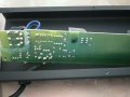
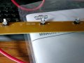
Here are some gut shots of the pedal :- IMG_2017_preview.jpeg I have followed simple diagrams for modifying my guitars but I would not know where to begin here. Any help would be greatly received.
 

Attachments

MrChips

Joined Oct 2, 2009
30,795
Perfectly doable.

You can go with a digital circuit, one that senses which button is pressed and then set/reset four flip-flops.

The easy one-chip solution is to use a microcontroller and measure the analog voltage at the RING. Then turn on/off the desired LED.
 

Thread Starter

Nik Evans

Joined Feb 8, 2018
5
Perfectly doable.

You can go with a digital circuit, one that senses which button is pressed and then set/reset four flip-flops.

The easy one-chip solution is to use a microcontroller and measure the analog voltage at the RING. Then turn on/off the desired LED.
Thanks for the reply. What components would you suggest?
 

Thread Starter

Nik Evans

Joined Feb 8, 2018
5
Perfectly doable.

You can go with a digital circuit, one that senses which button is pressed and then set/reset four flip-flops.

The easy one-chip solution is to use a microcontroller and measure the analog voltage at the RING. Then turn on/off the desired LED.
could i use an IC4043?
 

MrChips

Joined Oct 2, 2009
30,795
could i use an IC4043?
That could work with a logic gate solution.

However, you still have to tackle two fundamental problems:

(1) how to detect that a switch was pressed
(2) how to reset all other flip-flops without resetting the presently active flip-flop
 

Thread Starter

Nik Evans

Joined Feb 8, 2018
5
Thanks for the reply Mr Chips. I have also been looking at the Arduino Uno as it can also run from 3.3v hopefully could get it to run from the amps own supply, then would not need any batteries. I think programming may be easier than soldering???
Thanks for your time.
 

MrChips

Joined Oct 2, 2009
30,795
Thanks for the reply Mr Chips. I have also been looking at the Arduino Uno as it can also run from 3.3v hopefully could get it to run from the amps own supply, then would not need any batteries. I think programming may be easier than soldering???
Thanks for your time.
Yes, a microcontroller running off the 3.3V supply would be a viable solution.
From where I'm sitting, I would explore three contenders:

Arduino
Microchip PIC
Texas Instruments MSP430
 

Thread Starter

Nik Evans

Joined Feb 8, 2018
5
Thank you very much for being so helpful :) . I shall be digging into more research. If i get stuck i hope you dont mind if I post again? Thanks.
 

MrChips

Joined Oct 2, 2009
30,795
No problem. Glad to be of assistance.

If you are new to programming, you can easily find someone in your area who could program or help you program just about any microcontroller (MCU) to do the job.

Personally, I have more experience working with MSP430 than with Arduino or Microchip PIC MCUs.
For under £12 you can buy the TI MSP-EXP430G2 Launchpad which will allow you to program an MSP430G2553 MCU. The software is free and can be downloaded off the internet.

Once you have that set up on your computer, I can send you the program code to get your task implemented. All you will have to do is some soldering on a PCB protoboard.
 
Top