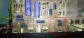
Yes, I know you don't have a schematic, and there doesn't seem to be anything available online. MrChips drew out the power amp section, but the problem seems to lie earlier in the circuitry. Drawing out a full schematic from your pictures is a time consuming process, but can be one.
If you have a smart phone, there is an app for that. All you would need is the plug (3mm stereo) to plug into into the phone’s audio jack. If you have a recent iphone, you would have to get an audio jack converter to plug into the lighting or USB C connector.
Anything that can produce a line level audio signal would work.
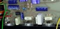
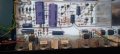
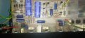
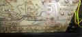
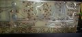
Can I get a couple new photo's of this area of the board? I need them straight on, all the way to the bottom of the board (many of the previous photo's have the bottom cut off). Try using a moderate light source behind the board so that the runs show through, but not so bright that the component color codes are washed out. Also, a photo of the run side of the board in the same area - again straight on and try to minimize reflections so the runs are clearly seen.
Well, yes, but since it seems that the first stage is working, AND a source of input signal is available, checking from input toward output would be simpler. It will provide the additional benefit of being able to immediately know the results of a repair.
Also, like I mentioned before, even with no circuit drawing at all, you can check for the signal at the output of each amplifier output. The output pin is well defined. And then, for any IC with no output, you can use a voltmeter to verify power supply voltages are present, and also check the DC voltage on the output terminal.
Can I get a couple new photo's of this area of the board? I need them straight on, all the way to the bottom of the board (many of the previous photo's have the bottom cut off). Try using a moderate light source behind the board so that the runs show through, but not so bright that the component color codes are washed out. Also, a photo of the run side of the board in the same area - again straight on and try to minimize reflections so the runs are clearly seen.
Ok, I am back.
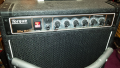
Your bass amp has six front panel controls, GAIN TREBLE BASS VOLUME | 62.5Hz 125Hz BASS EQ |
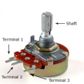
Each control pot (potentiometer) looks somewhat like this, looking at it from the front view.
There are three terminals 1, 2, and 3.
On the first GAIN pot, turn the knob fully clockwise.
Do the signal probe test on terminals 1, 2 and 3, while inputting signal from the guitar.
We are expecting to get full volume sound at terminals 2 and 3, nothing from terminal 1.
Can I get a couple new photo's of this area of the board? I need them straight on, all the way to the bottom of the board (many of the previous photo's have the bottom cut off). Try using a moderate light source behind the board so that the runs show through, but not so bright that the component color codes are washed out. Also, a photo of the run side of the board in the same area - again straight on and try to minimize reflections so the runs are clearly seen.
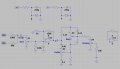
View attachment 307175
Here is what I see so far. That tone control arraignment looks odd to me, but it seems correct. Component values listed where I could read them.

 Facebook
 Google
 GitHub
 Linkedin

 .
.