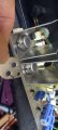
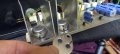
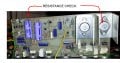
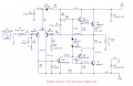
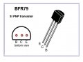
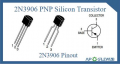
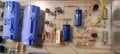
I think the 2M2906 (metal case) driver transistor is actually a 2N3906 (as shown) so it matches the 2N3904 driver transistor.
Then both little transistors are overloaded and produce distortion and smoke at high output levels and if the 2N3055 output transistors have normal but low gain.
Did the 2N3055 transistors come with transistor mounting hardware?
Did you use the insulating washers to mount the transistors to the heatsink?
Remove any insulating washers. The case of the transistors must be electrically bonded to the mounting nuts and bolts, i.e. the metal heatsinks are live, one at +40V and the other at speaker output voltage.
With the amp power cable unplugged, use the DMM on ohmmeter range and measure the resistance between the right most transistor case and the +40V rail at the bulk capacitor. You ought to be reading close to zero ohms.
With the amp power cable unplugged, use the DMM on ohmmeter range and measure the resistance between the right most transistor case and the +40V rail at the bulk capacitor. You ought to be reading close to zero ohms.
We misinterpreted the sign on your readings.
To avoid confusion, don't use -ve sign for anything else except to mean negative.
Don't leave out the + sign when the reading is positive. Sign is absolutely important.
BTW, 0.00V reading is not nothing. When the meter shows 0.00, say so. Do not say nothing.
Now we have to go back and analyse what all this means.
We misinterpreted the sign on your readings.
To avoid confusion, don't use -ve sign for anything else except to mean negative.
Don't leave out the + sign when the reading is positive. Sign is absolutely important.
BTW, 0.00V reading is not nothing. When the meter shows 0.00, say so. Do not say nothing.
Now we have to go back and analyse what all this means.
Two base-emitters in series make 1.2V to 1.4V.
There are a total of four base-emitters in series then four diodes are needed to avoid crossover distortion.
Two base-emitters in series make 1.2V to 1.4V.
There are a total of four base-emitters in series then four diodes are needed to avoid crossover distortion.
3 actually, but there are only two on the board, and by the voltage measurements they seem to be plain old single junction diodes. Remember this is a 'guitar' amp - low distortion may not be a priority.

 Facebook
 Google
 GitHub
 Linkedin