Ok so this is not a linear amplifier but the opamp acts as a comparator outputing the power rails?
How can I know that its outputs are saturated in this situation?
No, that’s a linear amplifier. Try inputting a triangular pulse and see what it does.
You can guess that because it has negative feedback.
0V in gives -6V out and 5V in gives -2V out, which wasn’t exactly the spec.
Absolutely. A general observation on pulse waveforms: The amplitude is rarely a critical parameter. Of more importance are the repetition rate, pulse width and rise and fall times.
Hello, currently I am using a this very long circuit to convert a 0-5V pulse into -2 to -6V volt pulse.
Is there a a good circuit which I could learn how to effectivly shift the pulse levels?and coltrol the high and low levels, while keeping the pulses rise and fall time?
As usual, you don't give the important details. How short are these pulses? What is the repetition rate (or, if not periodic, what is the closest that two pulses can occur to each other)? What is the pulse duration? What are the rise and fall times? How close do the output rise/fall times need to match the input rise/fall times? Since the amplitude of the input pulses is different than the output pulses, what is the definition of rise and fall time that you are using?
In post #24:
First calculate the volage at the op amp (+) input.
Then using that voltage for the (-) input, calculate the current through R3, which, due to negative feedback, must equal the current through R2.
From that you can calculate the output voltage.
A 20 ns rise and fall time is very fast. Again -- what is the definition of "rise time"? Is it 10%-to-90%? Is it time constant? Is it something else?
If the output is going 80% of the distance between -2 V and -6 V, in 20 ns, that's 3.2 V / 20 ns = 160 V/µs. That's pretty fast, but today there are a number of options that can do that.
it will be great to know one way you could reccomend ?
" If the output is going 80% of the distance between -2 V and -6 V, in 20 ns, that's 3.2 V / 20 ns = 160 V/µs. That's pretty fast, but today there are a number of options that can do that."
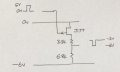
Hello Eric, I tried to analize your circuit to get mathematical formula Vout=F(Vin)
I used the virtual ground assumption of V-=V+.
but its not working so much
I got in the end Vout=6V and Vin cancels.
Where did I go wrong in the mathematical logic?
Thanks. View attachment 361184
it will be great to know one way you could reccomend ?
" If the output is going 80% of the distance between -2 V and -6 V, in 20 ns, that's 3.2 V / 20 ns = 160 V/µs. That's pretty fast, but today there are a number of options that can do that."
You haven't given anywhere near enough information to recommend a specific part. Go to DigiKey or some other similar site and use their product selectors to find suitable devices based your needs.
Or use one of the simpler circuits that have been suggested, being sure to find transistors that have the necessary bandwidth and sizing your resistors accordingly.
A lot will depend on what you are driving with this signal, which is yet something else that you've given no indication of.
Hello Wbahn, thank you very much .regarding solution in post 37 ,what is the limitation of this circuit.
seeing in digikey components Is choosing a black box.I only know the rise a fall and output pulse values requerment.
could you tell me an example for requirement and next level circuit that solves it so I could learn its inner logic?
Thanks.
The JFET circuit can manage 20ns with a J174 and lower resistor values. (About 60ns with the J177 and the resistors I drew) for a lot less money than an op-amp with the required slew-rate.
 Facebook
 Google
 GitHub
 Linkedin
 121.8 KB Views: 8


