Global Specialties Instruments - 20 MHz Sweep/Function Generator assistance

Thread Starter

CBTech_Joe

Joined Sep 9, 2020
39
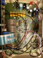
Hi everyone, brand new to the forum and I have a question. I am looking for a schematic for a Global Specialties Instruments 20 MHz Sweep/Function Generator. It has no model number on the case, and the main circuit board is marked FG1202-1. The 50 ohm output on the front panel does not work any more but the TTL and CMOS outputs are working fine. All other functions seem to be ok, but I would like to get it repaired and back in service. Any help would be appreciated.
 

dl324

Joined Mar 30, 2015
16,845
Welcome to AAC!

Have you tried contacting Global Specialties? Have you checked the back label? Sometimes they put the model number there.

The 50 ohm output on the front panel does not work any more but the TTL and CMOS outputs are working fine.
Someone probably overloaded the 50 ohm output. I had an old function generator of that type and it was either a resistor or transistor that needed to be replaced.
 

Thread Starter

CBTech_Joe

Joined Sep 9, 2020
39
Dennis,
Thanks for the reply, I suspect as you did that the output was overloaded. I did search the entire unit for a model number, and I checked the Global Specialties website for their discontinued equipment but was unsuccessful in finding any mention of this unit. How were you able to locate the faulty component in your example? I can't see any damaged components visually, and I don't have any documentation. I have traced the output BNC to the board, and it goes to solder connection on the main board labeled JP4. That location is surrounded by capacitors, a relay, and a few resistors. I may start checking resistor values, but they are still in situ.
 

MrChips

Joined Oct 2, 2009
30,708
If you cannot locate a circuit schematic, look at the coax cable coming off the 50Ω OUTPUT connector. Follow it back to where it is connected to the PCB. Take a photo of the components at that part of the PCB so that we can read the markings on the ICs.

Do you have access to an oscilloscope?
 

Thread Starter

CBTech_Joe

Joined Sep 9, 2020
39
If you cannot locate a circuit schematic, look at the coax cable coming off the 50Ω OUTPUT connector. Follow it back to where it is connected to the PCB. Take a photo of the components at that part of the PCB so that we can read the markings on the ICs.

Do you have access to an oscilloscope?
I think I found the schematics, I will post them here if I can figure out where they should be. I followed the cable back and the attached picture shows the location. The only chip in that location is an AD 811 which I believe is a video op amp. Not sure what that would be doing in circuit here.

I have an oscilloscope available it needed.
 

Attachments

MrChips

Joined Oct 2, 2009
30,708
Simply jumper across R76 and test for output.
How are you able to test for analog output at the 50Ω OUTPUT connector?
 

Thread Starter

CBTech_Joe

Joined Sep 9, 2020
39
Simply jumper across R76 and test for output.
How are you able to test for analog output at the 50Ω OUTPUT connector?
One scope in the guts looking for a signal and another hooked up to the 50Ω output. No joy yet. Might have taken out the IC as well. Still trying to locate it on the board.
 

schmitt trigger

Joined Jul 12, 2010
868
Check the signals on U15’s pin 10

The reason to use a video amp in the late 80s was that they were the only thing that was very fast, would drive a low impedance and would not cost an arm and a leg.
 
Check the resistors in the output. The relays could be toast at this age too.

U15 is likely toast from your measurements. it may have had a voltage fed back through the output.
 
Last edited:

Thread Starter

CBTech_Joe

Joined Sep 9, 2020
39
Ok, here is what I know. I DO have a signal on U15. It matches the control settings on the display for frequency and form, it is about 5V peak to peak. (I was using my old Tektronix and wasn't paying attention to settings.) Deducting points from myself for boneheadedness. Switched over to my Rigol (auto features are nice) and found it there. I am seeing a 250mV peak to peak signal at U24 pin 2. Checked power to U24. +15 and -15 present. Output appears to be noise. Looks like a bad resistor and a bad AD811 chip.
 

Thread Starter

CBTech_Joe

Joined Sep 9, 2020
39
Ok, here is an update. I have verified the rest of the components in the device that impact that area. I am reasonably certain the only two issues I have are the burnt out resistor (which shows no signs of damage) and the AD811AN chip. I have ordered the replacement chip (same specs mostly, different numbers as the original is obsolete and not stocked anywhere) and will update this thread when I receive and install the parts.

Thanks to everyone who assisted in this thread, and I have to say, it is kind of fun troubleshooting with people who have a clue. Not an everyday event for me.
 
Stuff could have been overloaded and changed value. Those resistance values are low and thus the relay contacts may or may not need to be looked at. Which I said before.

AD811: https://www.findchips.com/search/ad811

An OP-amp not used as a comparitor, can USUALLY checked with a voltmeter between the (+) and (-) input. the value measured should be close to zero.

FWIW:
There is always the inspection. You could find a sandwich in a VCR or a roach nest for instance. Cat hair on top of an audio amplifier. Rattles, like an electron tube out of it's socket. regulator for 1 15 kV supply at 1.5A.

Verify the customer's complaint.

Always check the power supplies. Ripple and value. Especially look at the ripple on the negative supplies.

So, far, I think you did well.
 
Top