Generator giving to high AC output .

Thread Starter

AkoAko

Joined Jan 26, 2020
12
I have bought a small 550 watt generator , unfortunatly i discovered that although the generator engine and alternator are in excellent condition i believe the automatic voltage regulator is faulty , i am getting 350 volts ac out and 21 volts dc when i should be getting 230 volts and 12 volts . Im not concerned about the DC voltage as i have no use for it however i would like to run a flat screen TV 110 watts and an electronic 24 volt battery charger from it consuming 350 watts and think both pieces of equipment would be damaged if i were to provide them with 350 volts .

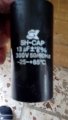
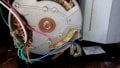
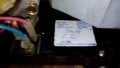
I was hoping there would be a simple inexpensive solution , i cant see any AVR anywhere and its not within the alternator as its clear the wires from it come directly out of the copper wingdings , the only external items are an AC to DC converter and a capacitor .

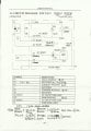
Its not possible to buy any parts for the generator as its no longer produced and already spent hours googling it .

Any suggestions would be grateful received .
 

AlbertHall

Joined Jun 4, 2014
12,625
How many wires come from the alternator?
If the alternator output is not regulated then the speed of the engine must be. What governs the engine speed?
 

Thread Starter

AkoAko

Joined Jan 26, 2020
12
The wires coming out of the generator can all be followed to where i would expect them to go , Switches , voltage gauge etc , nothing strange that i dont recognize apart from 2 that go to what looks like a large round plastic capacitor . The engine speed is supposed to be left with throttle in tick over position and governed by the load , the 350 volts are from slow running to max so i know its not engine revving to high because i opened the throttle with no load and revs didnt increase much at all , voltage remains exactly the same 350 volts .
 

AlbertHall

Joined Jun 4, 2014
12,625
There are a lot more than two wires coming from the alternator. What is that thing to the bottom right of the alternator (2 red wires and a blue wire)?
 

Thread Starter

AkoAko

Joined Jan 26, 2020
12
My multimeter is accurate , it has to be as its used for my solar system which is quite large but has other digital gauges on the inverted and solar controller which all correspond , the inbuilt Voltmeter on the generator only goes up to 300 volts and as soon as the generator is started it moved directly to the 300 volt stop .

I meant there are 2 wires from the capacitor , the alternator has more . The square thing at the bottom i thing is for AC to DC it has 2 AC and 1 DC connector .
 

Attachments

Thread Starter

AkoAko

Joined Jan 26, 2020
12
My multimeter is accurate , it has to be as its used for my solar system which is quite large but has other digital gauges on the inverted and solar controller which all correspond , the inbuilt Voltmeter on the generator only goes up to 300 volts and as soon as the generator is started it moved directly to the 300 volt stop .

I meant there are 2 wires from the capacitor , the alternator has more . The square thing at the bottom i thing is for AC to DC it has 2 AC and 1 DC connector .
The pink wire is the DC out and goes to the + 12 volt output terminal as it shows on the white label next to it , not sure if it can be read on the screenshot but its wired correctly , nothing inside has been touched , dont think the generator covers have ever been off before , the previous owner bought it new and used it for power during power cuts so its been run no more then 4 or 5 times to run a small TV , TV set top box and Standard lamp . Before selling it he did plug in a 900 watt disk cutter and sent me a short video of it running , im sure that in doing that he burnt out the automatic voltage controller wherever that is , its only explanation i can think off .
 

Thread Starter

AkoAko

Joined Jan 26, 2020
12
Video of it working with 900 watt Disc Cutter , its well above the 650 watt maximum and 550 watt normal working conditions .

Video wont attach .
 

Reloadron

Joined Jan 15, 2015
7,887
The wires coming out of the generator can all be followed to where i would expect them to go , Switches , voltage gauge etc , nothing strange that i dont recognize apart from 2 that go to what looks like a large round plastic capacitor . The engine speed is supposed to be left with throttle in tick over position and governed by the load , the 350 volts are from slow running to max so i know its not engine revving to high because i opened the throttle with no load and revs didnt increase much at all , voltage remains exactly the same 350 volts .
Small generators like this run at a constant speed based on number of poles. Normally 50 Hz units at 3,000 RPM and 60 Hz units at 3,600 RPM unless they are an inverter type generator. They have a governor to control engine speed under normal run conditions. The AVR (Automatic Voltage Regulator) is normally little more than a full wave bridge rectifier and a capacitor driving the field winding. The whole thing pretty much looks like this:

Gen.gif

The schematic is for a 4.0 KW US version but you get the idea as to voltage regulation on the field winding.

Ron
 

debe

Joined Sep 21, 2010
1,415
The capacitor is the voltage control, check it is good or just try an other one. This is a common cheap type of generator. The capacitor with the red marking is what controls the voltage.GMC.10.jpg
 

Attachments

Thread Starter

AkoAko

Joined Jan 26, 2020
12
Thank you both , not sure hoe to test the capacitor though , its has no + or - markings and only ever used multi meter for continuity and voltages , not sure it has the capability to test it , if it can be done with what i have and you could give me some pointers it would be appreciated . Was expecting the Voltage Controller to be something with several components , from what i read there were mentions of Diodes and Rectifiers , the cheap ones i found on Amazon were less than $10 but voltages shown were no more than about 250 volts ac so think would not cope with reducing 350 down to 230 .
 

Attachments

Thread Starter

AkoAko

Joined Jan 26, 2020
12
The multimeter only shows 1. when i set it to 2k on ohms range , it doesnt change by touching the capacitor contacts , if i touch the multimeter probes together it shows numbers that quickly decrease to .000 every time i do it but nothing changes at all touching Capacitor , is that an indication of anything ?
 

Reloadron

Joined Jan 15, 2015
7,887
When you check the capacitor with an ohmmeter you want the capacitor disconnected from the circuit. Checking a 10 uF 370 working volt AC cap I get about 2.0 Meg Ohm and it creeps up from there.

Ron
 

Thread Starter

AkoAko

Joined Jan 26, 2020
12
Shows 1. which i think means no circuit when 2M is selected then when touched to Capacitor connectors i watched it increasing to up to 1.985 then numbers disappear and i just see 1. again touching them again with probes reversed shows -.525 then all the way down to 0 then back up to 1.985 again . The same happens each time i change polarity of probes , whichever way i do it i get exactly the same results .
 

AlbertHall

Joined Jun 4, 2014
12,625
Shows 1. which i think means no circuit when 2M is selected then when touched to Capacitor connectors i watched it increasing to up to 1.985 then numbers disappear and i just see 1. again touching them again with probes reversed shows -.525 then all the way down to 0 then back up to 1.985 again . The same happens each time i change polarity of probes , whichever way i do it i get exactly the same results .
Well it is still a capacitor. Do you have another capacitor of similar value you can compare it to?
 

Thread Starter

AkoAko

Joined Jan 26, 2020
12
Unfortunately no i dont have any others at all . I do notice that once reached around the max of 1.985 ish , if i remove probe and then touch contacts again a second or two later a lower number shows and starts to increase , removing probe again before it reaches max of 1.985 ish again and another lower number , leaving probe then until reaches max then gives a reading of 1. , after that nothing else will show from touching contacts with probe unless i short them together then the numbers start from 1. to 1.985 all over again . Im sure the 1. it shows after reaching 1.985 ish or before touching anything with the probes is just zero .
I watched a video where the guy put the contact leads into 230 vold AC socket for a second to change a capacitor and there was a bang as the capacitor charged then touched leads together and another bang , he said it showed capacitor was working fine , was charging and discharging , haven't tried that yet .
 
Last edited:
Top