 Facebook
 Google
 GitHub
 Linkedin
Hi,
I seek help in understanding a phase generator circuit. This circuit creates 64 phases of the 100MHz input clock each separated by 156.25ps.
Effectively it is creating an output of 6.4GHz from the incoming 100MHz.
I am wondering how the output will look like
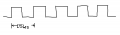
1) What would be the output like, will it be a continuous signal with time period of 156.25 ps? (as I have shown in the attachment)
2) What circuit elements are required to generate phases out of an incoming signal?
Thanks in advance,
Manish
I seek help in understanding a phase generator circuit. This circuit creates 64 phases of the 100MHz input clock each separated by 156.25ps.
Effectively it is creating an output of 6.4GHz from the incoming 100MHz.
I am wondering how the output will look like
1) What would be the output like, will it be a continuous signal with time period of 156.25 ps? (as I have shown in the attachment)
2) What circuit elements are required to generate phases out of an incoming signal?
Thanks in advance,
Manish
Attachments
-
 115.1 KB Views: 13


")


