Generating short 100V pulses

Thread Starter

hrs

Joined Jun 13, 2014
520
Hi,

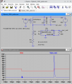
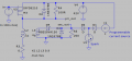
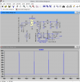
How would you generate 100V pulses of approximately 100ns at no more than 10kHz? A 42V power supply is available and the pulses must be triggered from a micro-controller that uses 5V and is referenced to the high side. The pulse current is about 450mA which is good.

For reference, I came up with something myself per attachment, though it may have more issues than I realize. It pulses at 100kHz but that's just to get more pulses in the waveform window.
 

Attachments

Thread Starter

hrs

Joined Jun 13, 2014
520
Do you want to have a rectangle pulse? 0V, 100V, 0V How fast for the rise and fall time? 10nS?
Do you want a half sign wave?
It doesn't need to be square per se. I was going for 'fast' edges so as to not blow up the mosfets but it's not a requirement otherwise. 10ns would be fine but up to 40ns rise and fall would also be ok. Half sine might be ok though I think square is probably better. The purpose it to ionize a tiny gap of demi water and then dump more current through the plasma from the 42V supply.
 

ronsimpson

Joined Oct 7, 2019
4,647
Note BOTIN is the inverse of TOPIN.
I just noticed you used low voltage MOSFETs. You need to change to 150 to 250V parts. Si4488dy
1718911842590.png
I know you do not have 100V supply and have no 10V supply. We can fix that later.
 

Attachments

joeyd999

Joined Jun 6, 2011
6,204
How about a simple flyback with a 100V zener clamp?

In fact, I don't think a clamp is required based upon you description of the application. Just a right-sized flyback transformer depending on your input voltage and timing requirements.
 
Last edited:

joeyd999

Joined Jun 6, 2011
6,204
I tried that but had ringing problems and the complexity of L and C is hard to explain. If I try it again, I will use the 42V supply as a clamp. (center tap or secondary clamp)
Use a flyback transformer, not an inductor. The ionization current should self-limit the peak voltage (I've done similar in the past).
 

Thread Starter

hrs

Joined Jun 13, 2014
520
Thanks Ron,

That looks much more accurate and repeatable than what I came up with. From tomorrow on I will go out for a few days and may not get back to this before monday. And I'll try to digest the LTC7061 datasheet first.
I just noticed you used low voltage MOSFETs. You need to change to 150 to 250V parts.
The MOSFET is 60V and only sees 42V AFAICT. Do you mean the diodes? I thought 150V would be enough headroom to do 100V but then I don't know much about electronics.

I know you do not have 100V supply and have no 10V supply. We can fix that later.
I have a 300VA ring transformer that was in a halogen light fixture that I intend to rewind to give unregulated rectified 42VDC. Maybe an extra winding can be used to give 10V if that helps.

How about a simple flyback with a 100V zener clamp?

In fact, I don't think a clamp is required based upon you description of the application. Just a right-sized flyback transformer depending on your input voltage and timing requirements.
In the thing I came up with I also tried a zener clamp and that worked in a sim but zeners that can handle significant current are huge, or at least no SMD candidate that I could find. When I think it's all ready I'll probably order PCA + assembly with as much SMD as possible.

Would fly-back imply an oscillator of some kind? I need it to be MCU triggered, 10kHz max but maybe as low as 1Khz.

Agree there is a limit when the load is there, you need a limit when the load is taken away.
Indeed it could happen that the gap is too large and 100V is too low to cause break-down.

Thank you gentlemen, I appreciate your support.
 

joeyd999

Joined Jun 6, 2011
6,204
Would fly-back imply an oscillator of some kind? I need it to be MCU triggered, 10kHz max but maybe as low as 1Khz.
No, I'd charge the primary an appropriate time prior to the pulse. The secondary impulse will occur upon turn-off of the primary switch.

You said you wanted nanoseconds. That'll give you nanoseconds. The ionization energy can by calculated by the inductance of the primary, and the peak charge current. The charge time is a function of inductance and input voltage. The output voltage will be capped by the voltage at which ionization occurs (similar to a spark gap). Size the winding ratio based on the max withstand voltage of the input transistor + headroom.
 

Thread Starter

hrs

Joined Jun 13, 2014
520
@ronsimpson How do you propose to generate the 10V and 100V supply.
I see that the TOPIN and BOTIN signals are referenced to the low side. I guess with this chip it must be that way.
 

Thread Starter

hrs

Joined Jun 13, 2014
520
Is it okay if the pulse goes above 100V?
Does it just go high until the gap breaks down and conducts?
The 100V sets a distance in the order of ~20um. When the gap is much bigger it should not break down so the voltage should not peak to 200V or 300V. But some +/- 10% ie. 90V to 110V would be fine. But if it can be for example zener clamped to 100V that would be best.
 

Thread Starter

hrs

Joined Jun 13, 2014
520
Would a pulse like this, using an inductor to provide the high voltage pulse, work for you?
I think that would work great! Some thoughts:
- The electrode needs to be at the more negative voltage. The high side will be connected to earth ground for safety. Then the MCU will be referenced to the high side and supplied by an LM79L05 or similar. So then maybe the same can be done as you propose but with a PFET.
- The ionization energy is speculative but what scant sources I can find suggest peak currents of 1A based on experiments. I have zero intuition for this.
 

joeyd999

Joined Jun 6, 2011
6,204
Does this capture the flyback principle? Is the inductance ratio about right?
The question is: does it work in your app?

Edit: you don't need R3 if you can precisely control the timing of the input pulse (with your MCU).

As an alternative, you can use R3 as feedback to adjust stored/discharged energy.
 

Thread Starter

hrs

Joined Jun 13, 2014
520
The question is: does it work in your app?
Agreed. My main concern is if the plasma channel will be stable long enough for D1 to turn on, see attached. I see no other option than to build it and see.
Edit: you don't need R3 if you can precisely control the timing of the input pulse (with your MCU).
That's interesting. I researched this and learned something. With R3=0 the sim goes to 9A in 390ns.
di/dt * t = 42V/1uH * 390ns = 16.4A. So I think an estimate for rDSon is still needed. With a 16MHz MCU I get a minimum on time of 62.5ns which equates to 2.6A steps (for rDSon=0), seems a bit coarse. Unless I misunderstand where you are going with this.
As an alternative, you can use R3 as feedback to adjust stored/discharged energy.
This is also interesting. I assume more energy input would keep the plasma channel around longer. Some control over this could be useful.
 

Attachments

Top