Does the burst have to be started at midpoint, eg. synchrous to trigger to start
the burst ?
When burst is off how many db down does 27 Mhz have to be from burst peak ?
Do bursts have to drive 50 ohms ?
Basically you gate an oscillator to do design. You can either gate the signal thru
a switch, or ground it in a voltage divider. 27 Mhz, my guess, probably wants to
come from a xtal oscillator....?
Building a circuit that gates the carrier starting and stopping exactly on a zero-crossing for exactly 2 ms is not complex, but it will be large. Basically, you are gating 54,240 cycles out of a 13.56 million total. This cannot be done with a simple monostable driving an analog gate, because a typical monostable cannot hold 1 part in 54,240 resolution.
If, OTOH, the 2 ms period does not have to be synchronous with the carrier and not terribly precise, then a 2 Hz oscillator and a 2 ms monostable can be built and gated with one quad NAND Schmitt trigger gate chip. The output controls whatever is needed for the required RF switch performance.
Does the burst have to be started at midpoint, eg. synchrous to trigger to start
the burst ?
When burst is off how many db down does 27 Mhz have to be from burst peak ?
Do bursts have to drive 50 ohms ?
Basically you gate an oscillator to do design. You can either gate the signal thru
a switch, or ground it in a voltage divider. 27 Mhz, my guess, probably wants to
come from a xtal oscillator....?
Yes bro i have generated the 27MHZ signal already from an crystal oscilotor now i want to switch this signal on and off .Morver i have also generated the pulses from 555 timer for on/off signal and aplied that on gate of Transistor (2n2222) but i am not getting the required signal on output.
Given the information in post #6, and the startup time of a crystal oscillator to come to stable amplitude and frequency compared to the 2 ms output window, I think a switch circuit is a better approach.
Given the information in post #6, and the startup time of a crystal oscillator to come to stable amplitude and frequency compared to the 2 ms output window, I think a switch circuit is a better approach.
Given the information in post #6, and the startup time of a crystal oscillator to come to stable amplitude and frequency compared to the 2 ms output window, I think a switch circuit is a better approach.
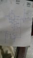
Your schematic shows you driving base of NPN directly, with no current
limiting or proper bias, from 555. That would burn out the NPN base junction
for sure.
You are trying to gate RF, the 27 Mhz signal, so to get effective off performance
you really should think about a pin diode type switch arrangement, links in earlier
posts. Of course if you do not need a lot of suppression of 27 Mhz when gate is
off you can consider some alternatives, eg. open collector switches to ground
diverting signal to ground.
Curious, what is the series LC trap on NPN collector to ground for ?
Once you get the bias correct for the output transistor (reference designators ?), a single 1N4148 diode between the 555 output and the base might be all that is needed to cut off the output transistor without affecting the oscillator freq.
Your schematic shows you driving base of NPN directly, with no current
limiting or proper bias, from 555. That would burn out the NPN base junction
for sure.
You are trying to gate RF, the 27 Mhz signal, so to get effective off performance
you really should think about a pin diode type switch arrangement, links in earlier
posts. Of course if you do not need a lot of suppression of 27 Mhz when gate is
off you can consider some alternatives, eg. open collector switches to ground
diverting signal to ground.
Curious, what is the series LC trap on NPN collector to ground for ?
Thanks for the time and response i just want turn on and off the 27MHZ signal throgh 555 timer i need a pulse rate of 1000 pulses per second and the pulse on duration should be 100 micro seconds i do not have to tranmit he wave just i need a pulsed magnetic field.I have craeated 1000 pulses from 555 timer but do not have any idea how to switch the 27MHz on and off as per my requirement
 Facebook
 Google
 GitHub
 Linkedin
 16.5 KB Views: 55