Gate Control For Frequency Counter

Thread Starter

radioshack5209

Joined Nov 25, 2020
68
Hi:

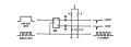
I am trying to find a simple circuit for controlling a frequency counter gate but the ones that I
have seen, all look like they wouldn't work.

The way I figure it is that you could use the positive edge of the time base signal to clear the
counter and open the main gate so that the input signal pulses (which may be analog converted
to a square wave) can be counted. Then the negative edge of the same time base signal could
be used to update the display.

Any help would be appreciated. Thanks.
 

Deleted member 115935

Joined Dec 31, 1969
0
That sounds about right,
what circuits have you seen that you don't think will work and why ?
 

Reloadron

Joined Jan 15, 2015
7,501
Below is a basic counter front end which originally showed up as a circuit by Forrest M Mimms circa early 80s.

Frequency Counter Front End.png
The clock is divided by a D flip flop and a CD40111 NAND gate Gates the incoming frequency to be counted and additional components form the Latch and RST out. Originally part of a simple six digit counter using MC14553 counter and MC4511 display driver (2 each). The circuit may give you a few ideas to work from.

Ron
 

Thread Starter

radioshack5209

Joined Nov 25, 2020
68
Below is a basic counter front end which originally showed up as a circuit by Forrest M Mimms circa early 80s.

View attachment 224211
The clock is divided by a D flip flop and a CD40111 NAND gate Gates the incoming frequency to be counted and additional components form the Latch and RST out. Originally part of a simple six digit counter using MC14553 counter and MC4511 display driver (2 each). The circuit may give you a few ideas to work from.

Ron
Thanks Ron. I don't have any CMOS devices at present.
 

WBahn

Joined Mar 31, 2012
29,976
Here is the first one. It can't discern the + edge from the - edge.
It can definitely tell +edge from -edge.

You won't get the pulses like it shows, however.

When the output of the FF isn't changing and has been static for some time, the voltage at the output of the circuit is determined by the voltage divider. Assuming a supply voltage of 5 V, the output would be about 3.4 V

Depending on whether this is TTL or CMOS, the HI output of the FF might be in that same region (if TTL).

Focusing on the Q output and assuming that the logic is CMOS, then the voltage change will be about 5 V between states. So on a LO-HI transition the output voltages will spike upward to about 8.4 V and on a HI-LO transition they will spike downward to about -1.6 V. I suspect the intent is that the part if TTL, which would spike upward to around 7 V and downward to around 0 V. Normally a diode is used with an edge detector to kill the unwanted spike by clamping it to no more than a diode drop outside the power rail.

The time constant for this edge detector, assuming that ".001" is a 0.001 uF" cap, would be around half a microsecond. That's if the FF can source and sink the 5 mA to 7 mA of current that would be needed at the beginning of the transition.
 

Thread Starter

radioshack5209

Joined Nov 25, 2020
68
It can definitely tell +edge from -edge.

You won't get the pulses like it shows, however.

When the output of the FF isn't changing and has been static for some time, the voltage at the output of the circuit is determined by the voltage divider. Assuming a supply voltage of 5 V, the output would be about 3.4 V

Depending on whether this is TTL or CMOS, the HI output of the FF might be in that same region (if TTL).

Focusing on the Q output and assuming that the logic is CMOS, then the voltage change will be about 5 V between states. So on a LO-HI transition the output voltages will spike upward to about 8.4 V and on a HI-LO transition they will spike downward to about -1.6 V. I suspect the intent is that the part if TTL, which would spike upward to around 7 V and downward to around 0 V. Normally a diode is used with an edge detector to kill the unwanted spike by clamping it to no more than a diode drop outside the power rail.

The time constant for this edge detector, assuming that ".001" is a 0.001 uF" cap, would be around half a microsecond. That's if the FF can source and sink the 5 mA to 7 mA of current that would be needed at the beginning of the transition.
Thanks WBahn
 

Reloadron

Joined Jan 15, 2015
7,501
Yes, the circle is just an invert.

Also, keep in mind when using chips like the 7408 IC is a QUAD 2-Input AND GATES and contains four independent gates each of which performs the logic AND function. When done ground or tie to VCC all unused inputs. Anyway yes, you can just use an inverter for the dot or any other inverting solution.

Ron
 

Thread Starter

radioshack5209

Joined Nov 25, 2020
68
Yes, the circle is just an invert.

Also, keep in mind when using chips like the 7408 IC is a QUAD 2-Input AND GATES and contains four independent gates each of which performs the logic AND function. When done ground or tie to VCC all unused inputs. Anyway yes, you can just use an inverter for the dot or any other inverting solution.

Ron
Thanks Ron. Also, if I use the solution that you offered (which I would prefer to use) can I just use TTL chips in place of the
CMOS chips or does that change the values of the resistors and caps?
 
Top