Facebook
 Google
 GitHub
 Linkedin
Hi guys,
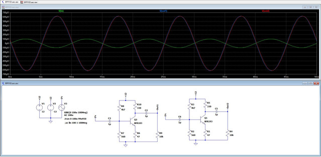
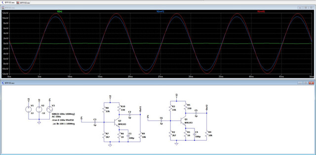
Today I was playing with LTspice and started testing with some transistors. I created two identical circuits with two very similar transistors namely the BFR183 and BFR193. I need some confirmation on reliability. I have seen these BJTs have incredible gain. With an input voltage of +/- 100uV I can get +/- 10mV or even 12mV. Since I'm still studying these simulators, I ask for confirmation if it is really possible to obtain such a high gain with this simple scheme and transistor. I am also attaching the datasheet links but it seems to me that the gain is too high when compared to the indicated parameters. The two transistors should be part of the standard LTspice library so you don't need an external file but I'm not sure because I use the extended libraries. So I also attach the .model text in case it helps. Thank you!
BFR183
BFR193
ASC File
.MODEL BFR183 NPN(IS=1.0345f ISE=1.6818E-14 ISC=1.3559f XTI=3 BF=115.98 NR=0.99543 IKF=0.14562 IKR=0.013483 XTB=1.5 VAF=14.772 VAR=3.4276 VJE=1.0792 VJC=1.1967 RE=1.3435 RC=0.20486 RB=2.5426 RBM=1.0112 IRB=0.00043801 CJE=2.3077E-14 CJC=4.6011E-13 XCJC=0.053823 FC=0.54852 NF=0.80799 BR=10.016 NE=1.2149 NC=0.85331 MJE=0.45354 MJC=0.3 TF=2.2746E-11 TR=1.0553n ITF=0.0018773 VTF=0.50905 XTF=0.36823 EG=1.11 VCEO=20 ICRATING=65m MFG=SIEMENS)
.MODEL BFR193 NPN(IS=2.738E-16 ISE=1.0627E-14 ISC=3.7409E-17 XTI=3 BF=125 BR=14.267 IKF=0.26949 IKR=0.037925 XTB=1.5 VAF=24 VAR=3.8742 VJE=0.70276 VJC=1.1828 RE=0.76534 RC=0.11938 RB=1.8368 RBM=1 IRB=0.00091763 CJE=1.1824f CJC=9.3503E-13 XCJC=0.053563 FC=0.72063 NF=0.95341 NR=1.4289 NE=1.935 NC=0.94371 MJE=0.48654 MJC=0.30002 TF=1.8828E-11 TR=1.0037n ITF=0.00096893 VTF=0.8 XTF=0.69477 EG=1.11 VCEO=20 ICRATING=80m MFG=SIEMENS)
Today I was playing with LTspice and started testing with some transistors. I created two identical circuits with two very similar transistors namely the BFR183 and BFR193. I need some confirmation on reliability. I have seen these BJTs have incredible gain. With an input voltage of +/- 100uV I can get +/- 10mV or even 12mV. Since I'm still studying these simulators, I ask for confirmation if it is really possible to obtain such a high gain with this simple scheme and transistor. I am also attaching the datasheet links but it seems to me that the gain is too high when compared to the indicated parameters. The two transistors should be part of the standard LTspice library so you don't need an external file but I'm not sure because I use the extended libraries. So I also attach the .model text in case it helps. Thank you!
BFR183
BFR193
ASC File
.MODEL BFR183 NPN(IS=1.0345f ISE=1.6818E-14 ISC=1.3559f XTI=3 BF=115.98 NR=0.99543 IKF=0.14562 IKR=0.013483 XTB=1.5 VAF=14.772 VAR=3.4276 VJE=1.0792 VJC=1.1967 RE=1.3435 RC=0.20486 RB=2.5426 RBM=1.0112 IRB=0.00043801 CJE=2.3077E-14 CJC=4.6011E-13 XCJC=0.053823 FC=0.54852 NF=0.80799 BR=10.016 NE=1.2149 NC=0.85331 MJE=0.45354 MJC=0.3 TF=2.2746E-11 TR=1.0553n ITF=0.0018773 VTF=0.50905 XTF=0.36823 EG=1.11 VCEO=20 ICRATING=65m MFG=SIEMENS)
.MODEL BFR193 NPN(IS=2.738E-16 ISE=1.0627E-14 ISC=3.7409E-17 XTI=3 BF=125 BR=14.267 IKF=0.26949 IKR=0.037925 XTB=1.5 VAF=24 VAR=3.8742 VJE=0.70276 VJC=1.1828 RE=0.76534 RC=0.11938 RB=1.8368 RBM=1 IRB=0.00091763 CJE=1.1824f CJC=9.3503E-13 XCJC=0.053563 FC=0.72063 NF=0.95341 NR=1.4289 NE=1.935 NC=0.94371 MJE=0.48654 MJC=0.30002 TF=1.8828E-11 TR=1.0037n ITF=0.00096893 VTF=0.8 XTF=0.69477 EG=1.11 VCEO=20 ICRATING=80m MFG=SIEMENS)
Last edited: