CE Amp Gain

LvW

Joined Jun 13, 2013
2,032
I cannot read your asc file. So I don`t know how the circuit looks like.
However, your calculation is not correct.
The transconductance is 0.04 A/V.
Moreover, does your circuit contain any signalfeedbck?
Is this in accordance with the ciruit diagram (and the simulation profile)?
 

Thread Starter

hobby2026

Joined Jun 13, 2026
9
I cannot read your asc file. So I don`t know how the circuit looks like.
However, your calculation is not correct.
The transconductance is 0.04 A/V.
Moreover, does your circuit contain any signalfeedbck?
Is this in accordance with the ciruit diagram (and the simulation profile)?
gm is calculated correctly at 0.04 I just wrote it down wrong. The attached spice file is good.
 

WBahn

Joined Mar 31, 2012
33,008
Hi

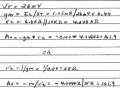
I did a spice sim for a CE amp. The gain according to spice is 88.9. My calculated gain is 161.9.
Can someone explain where I have gone wrong?
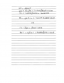
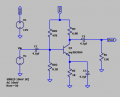
I have attached the spice file and the calculations.

Thanks.
1784420056968.png
1784420122563.png

Where does the 10 kΩ that you are putting in parallel with the 6.8 kΩ come from?

Seems odd that you use 0.40 A/V as your transconductance in three different places and don't catch the error. Makes me wonder how much attention you are paying to your work.

You need to always check your assumptions. You are throwing equations at a problem without verifying that the conditions needed for them to apply are met.

Just taking into account one of them results in a nominal gain of about 111.
 

0ri0n

Joined Jan 7, 2025
179
I did a spice sim for a CE amp. The gain according to spice is 88.9. My calculated gain is 161.9.
Can someone explain where I have gone wrong?
The simulated gain figure is @ 1kHz. Your calculated gain figure is different because you assume that RE || C3 is irrelevant which is not the case @ 1kHz.
 

ericgibbs

Joined Jan 29, 2010
21,502
hi hobby,
If your asc file includes non-standard models, EG: My2N3904, please include the Model parameters on the asc file circuit.

E
BTW: If you use an AC =1 value, the Bode plot will show the circuits actual output Gain in dB.
 

crutschow

Joined Mar 14, 2008
38,599
Your emitter bypass capacitor is too small.
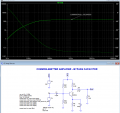
With a C3 of 470uF, the simulated gain is 150.6 when well above the low-frequency rolloff (below).
C3 and RE form a high-pass filter with their +3dB point being from the minimum low-frequency gain determined by the ratio of C3 and the parallel value of RC and RL.
The maximum gain is reached when the reactance of C3 is well below the intrinsic emitter resistance re, where re is Vt/Ie, Ie being the emitter current, and Vt being the thermal voltage of about 26mV at room temperature.

1784468133848.png
 
Last edited:
Top