I want to build this circuit that i found online but i want to have it give me a gain of 3, what resistors control the gain please and what is the equation to work it out?
I want to build this circuit that i found online but i want to have it give me a gain of 3, what resistors control the gain please and what is the equation to work it out?
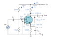
The first thing you need to consider is what your load is going to be. If you are planning to directly drive a speaker or other fairly low-impedance device, If your load will be at least 10x your collector resistor, then we can proceed. Let's assume that this is the case (which is a pretty iffy assumption) and that you will keep the collector resistor at 1.2 kΩ.
For a gain of three, you want the collector resistor to be three times the emitter resistor (and you want to remove the cap that is across the emitter resistor -- it is there to enable you to get very high gain while keep the bias current in check). That means you want the emitter resistor to be about 400 Ω (390 Ω is a standard resistor value that is almost certainly more than close enough for this). To get the quiescent collector voltage to be about Vcc/2 (or about 6 V), the emitter voltage will be about Vcc/6, or about 2 V. That means that the quiescent base voltage needs to be about 2.7 V. You bias resistors can be an order of magnitude larger than your collector and emitter resistors, up to perhaps 50x. The best choices within that range depend on what you want your cutoff frequency to be for the input filter, which fixes the relationship between the input coupling capacitor and the bias resistors. To get 2.7 V, we need the ratio of the top bia resistor, Rt, to the bottom one, Rb, to be:
2.7 V = 12 V * (Rb / (Rt + Rb)) (Voltage divider equation)
(Rt + Rb) / Rb = 12 V / 2.7 V
(Rt/Rb) + 1 = 4.44
Rt/Rb = 3.44
Let's choose Rt to be 27 kΩ (a standard value that is about 20x the collector resistor). That would make Rb ideally 7.83 kΩ, so we can choose either 7.5 kΩ or 8.2 kΩ. Let's go with 7.5 kΩ. since it's a bit closer.
No we need to deal with the frequency range. Assuming (and it is most definitely an assumption on my part) that you are interested in audio frequencies, we want to set the cutoff frequency of the input filter down around 20 Hz, though it can probably be somewhat above that depending on what the actual purpose is. But let's stick with 20 Hz as the cutoff frequency.
Instead of running the math around the filter frequency response, since I know that you don't like math, let's take a more brute force hatchet attack at it.
The cutoff occurs when the magnitude of the reactance of the input capacitor is equal to the effecting input resistance of the bias resistors, which is the parallel combination of them. Since one resistor is 3x to 4x the other, we can get away with just calling this the smaller of the two, or 7.5 kΩ (if we crank the numbers, we get 5.9 kΩ, so there's a noticeable difference, but not enough to cause much heartache).
The reactance of a capacitor is
Xc = -1/(2πfC), so we want
7.5 kΩ = 1/(2πfC) (the minus sign is thrown out because we are interested in the magnitude)
giving us
C = 1/(2π · 20 Hz · 7.5 kΩ) = 1.06 µF
So let's call it 1 µF.
For the output, if our load is 10 kΩ, we will end up with a slightly smaller value, but 1 µF will probably still do just fine.
Let's see what this gives us:
For a 1 kHz input signal, we get:
You can see that we have a pretty clean signal that is nicely symmetric, but that the gain is about 2.7 instead of 3. That's within 10% and is probably good enough. If we wanted to get closer quickly (sticking with the hatchet approach), we can reduce the emitter resistor by 10% and leave everything else the same, even though that will shift our bias point. That would ideally have us use a 351 Ω resistor. Our standard choices are 330 Ω and, if we are willing to use values from the E24 series instead of restricting ourselves to the E12 series, 360 Ω. But, if 10% isn't close enough, we probably should consider using a potentiometer in order to adjust the gain as needed.
Another thing we should consider is how well centered our quiescent point is. But I'll leave that for further discussion in case you are interested.
The first thing you need to consider is what your load is going to be. If you are planning to directly drive a speaker or other fairly low-impedance device, If your load will be at least 10x your collector resistor, then we can proceed. Let's assume that this is the case (which is a pretty iffy assumption) and that you will keep the collector resistor at 1.2 kΩ.
For a gain of three, you want the collector resistor to be three times the emitter resistor (and you want to remove the cap that is across the emitter resistor -- it is there to enable you to get very high gain while keep the bias current in check). That means you want the emitter resistor to be about 400 Ω (390 Ω is a standard resistor value that is almost certainly more than close enough for this). To get the quiescent collector voltage to be about Vcc/2 (or about 6 V), the emitter voltage will be about Vcc/6, or about 2 V. That means that the quiescent base voltage needs to be about 2.7 V. You bias resistors can be an order of magnitude larger than your collector and emitter resistors, up to perhaps 50x. The best choices within that range depend on what you want your cutoff frequency to be for the input filter, which fixes the relationship between the input coupling capacitor and the bias resistors. To get 2.7 V, we need the ratio of the top bia resistor, Rt, to the bottom one, Rb, to be:
2.7 V = 12 V * (Rb / (Rt + Rb)) (Voltage divider equation)
(Rt + Rb) / Rb = 12 V / 2.7 V
(Rt/Rb) + 1 = 4.44
Rt/Rb = 3.44
Let's choose Rt to be 27 kΩ (a standard value that is about 20x the collector resistor). That would make Rb ideally 7.83 kΩ, so we can choose either 7.5 kΩ or 8.2 kΩ. Let's go with 7.5 kΩ. since it's a bit closer.
No we need to deal with the frequency range. Assuming (and it is most definitely an assumption on my part) that you are interested in audio frequencies, we want to set the cutoff frequency of the input filter down around 20 Hz, though it can probably be somewhat above that depending on what the actual purpose is. But let's stick with 20 Hz as the cutoff frequency.
Instead of running the math around the filter frequency response, since I know that you don't like math, let's take a more brute force hatchet attack at it.
The cutoff occurs when the magnitude of the reactance of the input capacitor is equal to the effecting input resistance of the bias resistors, which is the parallel combination of them. Since one resistor is 3x to 4x the other, we can get away with just calling this the smaller of the two, or 7.5 kΩ (if we crank the numbers, we get 5.9 kΩ, so there's a noticeable difference, but not enough to cause much heartache).
The reactance of a capacitor is
Xc = -1/(2πfC), so we want
7.5 kΩ = 1/(2πfC) (the minus sign is thrown out because we are interested in the magnitude)
giving us
C = 1/(2π · 20 Hz · 7.5 kΩ) = 1.06 µF
So let's call it 1 µF.
For the output, if our load is 10 kΩ, we will end up with a slightly smaller value, but 1 µF will probably still do just fine.
You can see that we have a pretty clean signal that is nicely symmetric, but that the gain is about 2.7 instead of 3. That's within 10% and is probably good enough. If we wanted to get closer quickly (sticking with the hatchet approach), we can reduce the emitter resistor by 10% and leave everything else the same, even though that will shift our bias point. That would ideally have us use a 351 Ω resistor. Our standard choices are 330 Ω and, if we are willing to use values from the E24 series instead of restricting ourselves to the E12 series, 360 Ω. But, if 10% isn't close enough, we probably should consider using a potentiometer in order to adjust the gain as needed.
Another thing we should consider is how well centered our quiescent point is. But I'll leave that for further discussion in case you are interested.
Well i built the circuit on breadboard and thought i'll just use 0.1uf Caps input and output, i got a gain of 2.5, i then changed the caps to 1uf as you suggested and got a gain of 3 which is what i wanted, i never in this world thought about capacitance reactance etc.
There is more to this than i thought and clearly i have a lot to learn
In a very crude way, you can think of a capacitor as a frequency-dependent resistor. At low frequencies, the resistance is very high (at DC, it is an open-circuit), while as the frequency increases, the resistance goes down. It never goes to zero (that would require infinite frequency), but it gets arbitrarily small. If the resistance is very small compared to the other resistances in the circuit, it is basically a short circuit.
The biggest rate of change is when the resistance of the capacitor is the same as the effective resistance of the rest of the circuit (as seen by the capacitor). The frequency at which this happens is the "cutoff frequency".
The reverse is the case for an inductor. It is also a frequency-dependent resistor (in this crude explanation), but it's resistance increases with frequency such that it looks like essentially like a short circuit at or near DC and essentially like an open circuit at sufficiently high frequencies.
As a result, we can't just throw any size capacitor at a circuit in order to AC couple it. We don't just kill the DC component of the signal, we block all frequencies significantly below the cutoff frequency and pass all frequencies significantly above it. For frequencies within a decade (a factor of ten) of the cutoff frequency, the amplitude very dependent on the exact frequency, which is why we place the cutoff frequencies well away from the frequencies we want to retain with little attenuation.
As you can see, there is a lot of math involved, so even if you hate math, you are going to need to learn how to do it well enough if you want to make significant headway in learning electronics.
In a very crude way, you can think of a capacitor as a frequency-dependent resistor. At low frequencies, the resistance is very high (at DC, it is an open-circuit), while as the frequency increases, the resistance goes down. It never goes to zero (that would require infinite frequency), but it gets arbitrarily small. If the resistance is very small compared to the other resistances in the circuit, it is basically a short circuit.
If you want to do it without the coupling capacitor, your input signal would have to have a DC offset that matched very closely the bias point of the amplifier. In fact, you wouldn't need the bias resistors at all as your signal would have to supply it. By removing the low-frequency component from both the input and output signals, it decouples the low-frequency bias signal, generated by the bias resistors, from the high-frequency information signal, provided by the signal source. It also makes it so that the DC level of the signal source isn't a factor, meaning that the signal can go above or below the power supply rails of the amplifier without causing any problems.
Designing and implementing DC-coupled amplifiers is a much more challenging task.
.............. also makes it so that the DC level of the signal source isn't a factor, meaning that the signal can go above or below the power supply rails of the amplifier without causing any problems.
Designing and implementing DC-coupled amplifiers is a much more challenging task.
Since the TS has not specified any other requirements than "a gain of 3", assuring optimum operation is not required.
The secret to having a requested design meet all of the desired specifications begins with clearly stating all of the desired specifications. (CAUTION!!! This is a nessesary, but not sufficient, requirement.)
 Facebook
 Google
 GitHub
 Linkedin
 46.2 KB Views: 31


