 Facebook
 Google
 GitHub
 Linkedin
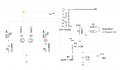
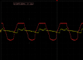
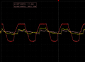
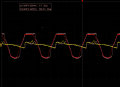
So I have a slightly modified Royer oscillator circuit that is driving a high voltage RF output for a frequency based medical device. The transformer has a center tapped primary coil with a center tapped feedback coil driving it so that the system runs at the resonant frequency of the saturated coil. I am not a circuit designer but I understand the basics of how this circuit works. I have begun to tinker with the value of the capacitors @ C8 and C9 and notice that it does change sensation of the output signal on our wand but it doesn't seem to be changing the frequency or the waveform of the output, which is a sine wave, or the waveform of the feedback coil. So I am wondering if anyone can tell me what changing these capacitors should affect so I can look for it and hopefully be able to optimize the output. during my "tuning" I have used capacitor values for C8 and C9 ranging from 30nF to 147nF and found that 139nF "feels" best but I would like to understand more about parameter what I am actually changing. I am posting some scope files with various values in C8 and C9 with the Yellow and Red waveforms measured at the corresponding scope probes located at the Yellow and Red circles on the schematic. The scope files have 30nF, 50nF and 100nF values installed for each capture but the feedback wave in Red basically doesn't change. The output to the primary wave in Red has a slight phase shift but doesn't really cause a change in the feedback waveform. Thanks in advance for your input.
Attachments
-
 93.8 KB Views: 30
 -
 14.8 KB Views: 26
 -
 17.8 KB Views: 21
 -
 18.1 KB Views: 17


