Facebook
 Google
 GitHub
 Linkedin
millwood
- Joined Dec 31, 1969
- 0
*always*? really?The issue of whether the transformer parasitics would be material was first mentioned in connection with this thread. For a 60Hz transformer at the power level under discussion in this thread and in a capacitor input filter, the transformer parasitics will always be material.
I have not encountered one single such case, but I guess I missed the memo,
") .
.I don't dispute the fact that they do. I dispute the notion that they are *always* material.Even though you may not have encountered them, they exist.
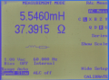
I don't dispute the methodology. I just have doubts about the measurements. I have a Signal transformer, dpc-12-2000, 24vac, 12vct@2amp. a small (tiny) transformer. It measures less than 1ohm dc resistance on the 2ndary (or 0.5ohm dc resistance per 2ndary winding), and about 60ohm dc resistance on the primary.In the circuit in this thread, run the simulation without the series 37Ω, but with the 5.6 mH series inductance.
I put the primary in serial with a 25w 110v light bulb and shorted the 2ndary. I got about 10vac across the primary.
If the transformer were a 60ohm resistor, the reading would have been 11 - 12v.
doesn't that suggest that the transformer is fairly close to be ideal? and the thing is just the size of a small chicken egg.
if you have seen a 1mh or a 2mh choke, you will absolutely question the reading of 5.6mh leakage inductance from a "tiny" transformer too.
those tube guys would be extremely delighted to get that much inductance out of a tiny transformer / choke, leakage or otherwise.