Full-Wave Bridge Rectifier Filter + Regulator DC Power supply

millwood

Joined Dec 31, 1969
0
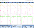
here is a quick sim. our calculations are pretty accurate:

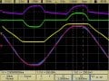
ripple: from 32.4v down to 29.3v, or 3.1v.

time decay: from 45.9ms to 54m, a total of 8ms.

the current going through the Rs resistor is just over 20ma.
 

Attachments

The Electrician

Joined Oct 9, 2007
2,970
For what it's worth - this is how I solved it.

This gives a ripple of 3.18V - and an average capacitor voltage of 30.96V.
Calculating an exponential discharge is gives a slightly more accurate result, but I think your calculation suffers a greater error because you have assumed that the discharge begins at Vmax. It actually begins a little later than that. The initial slope of the discharge line has to be tangent to the sine wave, and that point is later than Vmax.

See the attached analysis, done by Jim Thompson. He assumes a linear discharge, which is close to the truth for the given time constant.
 

Attachments

Jony130

Joined Feb 17, 2009
5,488
I see one problem, that these calculations don't take into account the
transformer parasitic parameters.
Especially the secondary voltage strongly depend on a load current and transformer "stiffness".
And voltage losses in a rectifier diodes can reach 1V for a diode or even more.
And that's why this simple calculations ( U=(I*t/C) ) are good enough for a practical point of view.
 

millwood

Joined Dec 31, 1969
0
I think your calculation suffers a greater error because you have assumed that the discharge begins at Vmax. It actually begins a little later than that. The initial slope of the discharge line has to be tangent to the sine wave, and that point is later than Vmax.
that's only true to the extent that there is some form of (material) resistance so the cap isn't fully charged at the peak, or the discharge of the capacitor is significant.

I cannot quantify the difference but I would venture to say that it is minor.
 

millwood

Joined Dec 31, 1969
0
I see one problem, that these calculations don't take into account the
transformer parasitic parameters.
because they are unknown here and they are tough to factor in and they are not likely to have any material impact in this cussion.

And voltage losses in a rectifier diodes can reach 1V for a diode or even more.
yes but that's unlikely for a circuit that is draining an average current of 20ma, and peak current through the diode of 200ma. I would be surprised if the datasheet for any reasonably specified mains diode would be anywhere close to 1v Vfwd.

And that's why this simple calculations ( U=(I*t/C) ) are good enough for a practical point of view.
most of these types of discussion are for educational purposes and I think as long as we know how to get to a reasonably good answer, 99% of the time, that's good enough, :).

in the end, tnk did get the most accurate answer.
 

The Electrician

Joined Oct 9, 2007
2,970
that's only true to the extent that there is some form of (material) resistance so the cap isn't fully charged at the peak, or the discharge of the capacitor is significant.
Think about it. If the sine wave voltage is greater than the cap voltage would be if it were free to discharge starting at the peak of the sine wave, then the sine will hold up the cap voltage until the rate of decrease of the sine wave just equals the rate of decrease of the cap voltage due to the load.

Make the cap 5 uF and in simulation you can clearly see that the cap voltage is still following the input sine wave until about 1 millisecond after the sine wave peak.

See the attachment with input sine wave and cap voltage in the top plot and cap current in the bottom plot (the cap is 5 uF).

And, yes, the effect is minor. Also, the assumption that the discharge characteristic is not linear, but rather exponential, is a minor effect when the cap is 47 uF, but can clearly be seen when it's 5 uF.
 

Attachments

millwood

Joined Dec 31, 1969
0
Make the cap 5 uF and in simulation you can clearly see that the cap voltage is still following the input sine wave until about 1 millisecond after the sine wave peak.
that is correct. using a smaller cap, or introducing a ESR to the cap does the same thing: it accelerates its discharging, or slowing down its charging.

another way to say it is that the smaller / less perfect cap cannot hold the rail as well as a bigger / more perfect cap.

But end of the day, the dominating factor here is the rectified ac: regardless of how fast our tinny / imperfect cap discharges, the voltage across the cap will not be less than that of the rectified ac.

the assumption that the discharge characteristic is not linear, but rather exponential, is a minor effect when the cap is 47 uF, but can clearly be seen when it's 5 uF.
true as well. the larger the cap, the longer the time constant, and the more "linear" the discharging looks like in a given period of time.
 

The Electrician

Joined Oct 9, 2007
2,970
But end of the day, the dominating factor here is the rectified ac: regardless of how fast our tinny / imperfect cap discharges, the voltage across the cap will not be less than that of the rectified ac.
You should say "...the peak voltage across the cap will not be less than that of the rectified ac." How fast or how long the cap discharges has an effect on the minimum voltage across the cap.

The effect I've described causes the minimum voltage across the cap to be higher than it would be if the discharge ramp started at exactly the peak of the sine wave voltage (because the cap is discharging for a shorter time), and the ripple voltage is therefore slightly less.
 

The Electrician

Joined Oct 9, 2007
2,970
that is correct. using a smaller cap, or introducing a ESR to the cap does the same thing: it accelerates its discharging, or slowing down its charging.
How can introducing an ESR "accelerate its discharging", while also "slowing down its charging"? Adding ESR increases the time constant for both charging and discharging, doesn't it?
 

The Electrician

Joined Oct 9, 2007
2,970
because they are unknown here and they are tough to factor in and they are not likely to have any material impact in this cussion.
It's true that in an academic problem like this, they are unknown, but they will have a substantial impact on the performance.

In small power supplies like this, the leakage inductance and winding resistance will be important parasitics. I measured a 1/2 amp rated small transformer, 24 VAC output. The winding resistance is 37Ω and the leakage inductance is 5.6 mH, referred to the secondary.

Inserting these values in series with the AC source, the simulation gives a ripple voltage of 2.2 V P-P, a substantial change from the value without these parasitics.
 

t_n_k

Joined Mar 6, 2009
5,455
Calculating an exponential discharge is gives a slightly more accurate result, but I think your calculation suffers a greater error because you have assumed that the discharge begins at Vmax. It actually begins a little later than that. The initial slope of the discharge line has to be tangent to the sine wave, and that point is later than Vmax.

See the attached analysis, done by Jim Thompson. He assumes a linear discharge, which is close to the truth for the given time constant.
Thanks for your (usual) perceptive insights Electrician - and those from other members as well. Thanks also for the analysis by Jim Thompson - I tip my proverbial hat to a greater & admirable intellect!
 

millwood

Joined Dec 31, 1969
0
It's true that in an academic problem like this, they are unknown, but they will have a substantial impact on the performance.
they *can* have a substantial impact, but they *may* not.

I measured a 1/2 amp rated small transformer, 24 VAC output. The winding resistance is 37Ω and the leakage inductance is 5.6 mH, referred to the secondary.
I am not that familiar with leakage parameters of a transformer but I would be really interested in learning from you what they mean, how they are measured and why they would have such a big impact here. Just by looking at the numbers, 5.6mh inductance is a huge number.
 

millwood

Joined Dec 31, 1969
0
How can introducing an ESR "accelerate its discharging", while also "slowing down its charging"? Adding ESR increases the time constant for both charging and discharging, doesn't it?
it was talking about two factors (smaller capacitance and high ESR) on the discharging and charging of a capacitor, respectively.
 

millwood

Joined Dec 31, 1969
0
You should say "...the peak voltage across the cap will not be less than that of the rectified ac."
no. At any point in time, the voltage across the cap will not be less than that of the rectified ac. the reason is simple: the rectified ac has far lower impedance (0 ideally) than the resistor / zener network. so if the capacitor were to be "overly" discharged to a point where the voltage across the capacitor is lower than that of the rectified ac, the rectified ac will start to provide current to the resistor / zener network, bringing UP the voltage across the capacitor, until the power where the two are equal.

The effect I've described causes the minimum voltage across the cap to be higher than it would be if the discharge ramp started at exactly the peak of the sine wave voltage (because the cap is discharging for a shorter time), and the ripple voltage is therefore slightly less.
the impact is very small. in my simulation, the "delay" is about .2ms. as I lost 3v over 8ms (0.4v/ms), .2ms will reduce the ripple by less than 0.1v. or 3%.
 

The Electrician

Joined Oct 9, 2007
2,970
no. At any point in time, the voltage across the cap will not be less than that of the rectified ac. the reason is simple: the rectified ac has far lower impedance (0 ideally) than the resistor / zener network. so if the capacitor were to be "overly" discharged to a point where the voltage across the capacitor is lower than that of the rectified ac, the rectified ac will start to provide current to the resistor / zener network, bringing UP the voltage across the capacitor, until the power where the two are equal.
I left out a word; I meant to say "You should say "...the peak voltage across the cap will not be less than that of the peak rectified ac." How fast or how long the cap discharges has an effect on the minimum voltage across the cap."

I was concerned with the issue of whether the capacitor voltage starts to decrease at the peak of the sine wave or not. I was alluding to the fact that the cap voltage does not begin to decrease exactly at the peak of the sine wave. The slope of the cap voltage there doesn't have a cusp, as tnk's pdf files shows.

Your comment "the voltage across the cap will not be less than that of the rectified ac" was apparently referring to all times; I thought you were referring to the behavior at the peak. Yes, of course, "the voltage across the cap will not be less than that of the rectified ac" at all times; that goes without saying.


the impact is very small. in my simulation, the "delay" is about .2ms. as I lost 3v over 8ms (0.4v/ms), .2ms will reduce the ripple by less than 0.1v. or 3%.
Several of these "exact" effects discussed in this thread are small, but it's good to recognize them in the "academic" setting.
 

The Electrician

Joined Oct 9, 2007
2,970
they *can* have a substantial impact, but they *may* not.
They definitely "will". Real transformers wound on silicon steel laminations, using winding techniques required to meet safety requirements don't have good enough coupling between primary and secondary to avoid noticeable leakage inductance, and of course, the resistance of the wire causes some unavoidable series resistance.

Typically, a large transformer might experience a decrease of a few percent in output voltage at rated current due to these parasitics.

A very small transformer (wall wart size) might lose 25% or more at rated current.


I am not that familiar with leakage parameters of a transformer but I would be really interested in learning from you what they mean, how they are measured and why they would have such a big impact here. Just by looking at the numbers, 5.6mh inductance is a huge number.
There's an exposition here: http://claymore.engineer.gvsu.edu/~johnsodw/egr325mine/paper2/paper2.html

They are measured by using an LCR meter. The meter applies a 60 Hz AC voltage to a winding; I measured at the secondary of the small transformer I referred to in another post. The primary is shorted, and the meter measures the impedance at the secondary and displays the impedance as a series inductance and resistance (Xeq and Req at the URL above).

The 5.6 mH is large, but that's because the transformer is very small. I have another somewhat larger (60 VA) transformer, and the same measurement gives .43 mH and 1.3Ω, referred to the secondary.

Typically however, almost any transformer you would find in a piece of equipment of a size such that a person could pick it up, will have parasitics that are sufficient to affect the diode current in a capacitor input filter.

If you have your simulation show the diode current, you will see that it's almost a triangular waveform (the image I attached to post #26 shows that). If you add the 5.6 mH and 37Ω in series with the AC input, you'll see the diode current looking like the top part of a sine wave.

I"ve attached a scope capture of the diode current waveform in a 100 VA bridge/capacitor input circuit. The orange waveform is the input to the transformer. It's a near perfect sine wave which I got from an audio power amp at 60 Hz; the real grid voltage is flat-topped.

The green waveform is the diode current, and the purple waveform is the voltage across the secondary of the transformer.

Notice that when the diode is conducting, the secondary voltage is clipped severely. This couldn't happen if the transformer didn't have a non-zero equivalent series impedance.

The filter cap is large enough that the voltage across it doesn't change much while the diode is conducting (low ripple, in other words), because the transformer doesn't have a low enough output impedance to force enough current into the cap to make its voltage follow the sine wave.

Even if the transformer could do that, the conduction angle would be much smaller, and the diode current would be even more peaky, and there wouldn't be much of a sine wave of voltage across the cap.

The theoretical example we've been analyzing in this thread assumed a perfectly stiff AC voltage source.

The second image is a bridge/capacitor input filter without a transformer; the bridge is connected directly to grid. The red waveform is the grid voltage and the green waveform is the diode current.

Without a transformer (the pole pig is a big guy, with proportionately smaller parasitics) the diode current is almost a triangle wave, as in the theoretical case we've been discussing.
 

Attachments

millwood

Joined Dec 31, 1969
0
They definitely "will".
whether they *will* or not depends on if the imperfection is material.

having dealt with various types of transformers in various applications, I have yet to find leakage inductance or capacitance to be of a real concern for me.


Typically, a large transformer might experience a decrease of a few percent in output voltage at rated current due to these parasitics.

A very small transformer (wall wart size) might lose 25% or more at rated current.
transformer regulation isn't a new thing and is primarily due to winding resistance.

so which measurement would your 5.6mh figure correspond to? serial or parallel inductance in that chart? what did you mean when you said "in reference to the 2ndary"?
 

millwood

Joined Dec 31, 1969
0
I"ve attached a scope capture of the diode current waveform in a 100 VA bridge/capacitor input circuit.
the waveform is like that primarily because of winding resistance in the 2ndary, and you can easily simulate that.

but 2ndary windingn resistance for a power transformer is tiny, typically less than 1ohm.

however, it can become a problem if the filter capacitor is very large: so large that the diode only conducts during a very short period of time, thus causing the current to spike significantly.

it is quite typical for the diodes to conduct only 10% during its cycle. That's why mains rectifiers usually have their peak current ratings 10 or 20x higher than its average ratings: so they can survive those situations.

leakage inductance plays a different role that has not shown up in the discussion yet.
 

The Electrician

Joined Oct 9, 2007
2,970
whether they *will* or not depends on if the imperfection is material.
The issue of whether the transformer parasitics would be material was first mentioned in connection with this thread. For a 60Hz transformer at the power level under discussion in this thread and in a capacitor input filter, the transformer parasitics will always be material. Using the values I measured for a typical very small transformer, in simulation the ripple voltage decreased from 3.1 volts to 2.2 volts, and the diode current became much less peaky. That's material. No transformer that small can do better without being wound with superconducting wire.

having dealt with various types of transformers in various applications, I have yet to find leakage inductance or capacitance to be of a real concern for me.
Even though you may not have encountered them, they exist. For example, in a 60 Hz inverter application, the voltage applied to the primary may be a square wave. The leakage inductance is primarily responsible for slowing the rise and fall times of the output square wave.

In the circuit in this thread, run the simulation without the series 37Ω, but with the 5.6 mH series inductance. The diode current is changed from a nearly triangular current into a much rounder waveform with a lower RMS value giving less diode heating. For this particular transformer, the series resistance is larger than the series reactance, but even if the transformer could have been wound with superconducting wire (zero winding resistance), the leakage inductance would have had the effect seen in the simulation. See the attached image showing the current in the diode without and with 5.6 mH of inductance (but without the 37Ω resistance) placed in series with the AC source.


transformer regulation isn't a new thing and is primarily due to winding resistance.
I didn't suggest that it was a new thing. When you say "transformer regulation isn't a new thing and is primarily due to winding resistance." without any qualification, it sounds like you are suggesting that this is the case for all transformers. That isn't true; it depends on the size and construction of the transformer. In small transformers, the winding resistance typically dominates, whereas in larger transformers, leakage inductance becomes dominant.

For example, in a 2.5 kW inverter transformer I have, at 60 Hz the equivalent series reactance is 1.24Ω and the equivalent series resistance is .4Ω, referred to the secondary. The leakage reactance dominates.

I don't have access to a really big transformer, but taking an example from the classic text, "Magnetic Circuits and Transformers", a 100kva transformer measured 1.51Ω reactive and .58Ω resistive; again, the leakage reactance dominates for a large transformer.


so which measurement would your 5.6mh figure correspond to? serial or parallel inductance in that chart? what did you mean when you said "in reference to the 2ndary"?
As I said in post #36, "The primary is shorted, and the meter measures the impedance at the secondary and displays the impedance as a series inductance and resistance (Xeq and Req at the URL above)."

When measuring the equivalent impedance of a transformer, the measurement can be made by shorting the secondary and measuring the impedance at the primary (this would be indicated by the phrase "referred to the primary), or by shorting the primary and measuring at the secondary ("referred to the secondary).

When you make a measurement of this sort, the resistance of the shorted winding is transformed by the square of the turns ratio and effective placed in series with the resistance of the unshorted winding.

In the cited URL, you see in figure 1 that no winding resistance is shown on the secondary side; it has been referred to the primary and is included in Req.

As the author says, "...all parameters have been moved to the primary side of the ideal transformer".

The very small transformer I measured has 231Ω of DC resistance in the primary and 16.2Ω of DC resistance in the secondary. So where did the 37Ω come from? The primary resistance is transformed to 20.8Ω by the square of the turns ratio (10:3) and appears in series with the resistance of the secondary when the secondary impedance is measured with the primary shorted.
 

Attachments

The Electrician

Joined Oct 9, 2007
2,970
the waveform is like that primarily because of winding resistance in the 2ndary, and you can easily simulate that.
Yes, I did simulate it, and for this very small transformer the winding resistance dominates the equivalent series impedance, but the effect of the leakage inductance can be seen in simulation as shown in the image attached to my previous post.

but 2ndary windingn resistance for a power transformer is tiny, typically less than 1ohm.
Without any qualification this would seem to be a universal assertion about all power transformers, and as such it just isn't true; I'm sure you know that. The small transformer I measured has 16.2Ω secondary resistance.

But the secondary resistance isn't the only concern: the primary resistance of a well-designed transformer will be about the same as the secondary resistance, when it's referred to the secondary. So the transformer's regulation should be affected by the primary resistance to about the same extent as by the secondary resistance.

This is why the equivalent series impedance is measured by shorting one winding and measuring at the other winding. That way the DC resistance of both windings in included in the measurement, as well as the leakage reactance.

however, it can become a problem if the filter capacitor is very large: so large that the diode only conducts during a very short period of time, thus causing the current to spike significantly.

it is quite typical for the diodes to conduct only 10% during its cycle. That's why mains rectifiers usually have their peak current ratings 10 or 20x higher than its average ratings: so they can survive those situations.
It's not as bad as you think. In the simulation reduce R3 to zero, make R2=1Ω, change C1 to 100,000 uF with zero ESR and change the diodes to 100 amp diodes. When I run this simulation, I get narrow 250 amp peak diode currents. But, now add .01Ω in series with the AC source and the peak current is reduced to 160 amps. With .1Ω series resistance, the peak current is reduced to 80 amps and the conduction angle is substantially widened.

Reduce the series resistance to zero and add a series inductance of 100 uH; the diode peak current is reduced to 95 amps, and the pulse is even wider than with .1Ω of resistance.

With .1Ω of resistance and 100 uH of inductance, the peak current is reduced to 70 amps and the diode conducts for about 4.5 mS, and the wave shape isn't very peaky at all.

With really large capacitances, the transformer parasitics become ever more important, and prevent extremely narrow diode current pulses.

I once decided to see if I could get a very narrow diode current pulse in a real capacitor input power supply, so I used a bridge of high current diodes and 100,000 uF of capacitance in a supply capable of about 200 watts. I lightly loaded it and captured the various waveforms as shown in the attachments.

The first image is with 4700 uF of capacitance and second is with 100,000 uF.

The red trace is the grid waveform, the green trace is the diode current, the yellow trace is the transformer secondary waveform and the purple trace is the ripple voltage.

Note the scale change between the two images. The purple trace is at 2 V/cm in the first image with 4700 uf, and changes to 100 mV/cm in the second image with 100,000 uF.

I had not expected this result; I expected a very peaky diode current. It was as a result of this experiment that I became aware of how the transformer parasitics become the determining factor when the filter capacitance becomes very large. You should try it yourself.

It's the result of millions of capacitor input power supplies that the grid waveform is flat topped. That fact also prevents extremely peaky diode currents even with insanely large filter caps.

leakage inductance plays a different role that has not shown up in the discussion yet.
I think it has shown up; at least I have discussed it and shown its effects.
 

Attachments

Top