Frequency Response of Band pass filter

Thread Starter

naickej4

Joined Jul 12, 2015
206
Hello All,

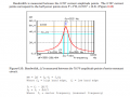
I found this filter question in a pass exam for DSP and I have forgotten most of my Circuit Analysis stuff from last year. Please can someone help me to check my work and possibly refresh my memory on some concepts that I have missed out.

upload_2016-10-24_19-7-34.png

I do remember vaguely that the Center Frequency is also know as Resonant frequency (Please correct me if I am wrong).
But my main problem comes when calculating the bandwidth, was the calculating the Corner Frequency also finding the bandwidth?

I truly can not remember much but if this does appear in the test on I might be in trouble.

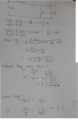
Please find my detailed solution ( forgive my camera quality on my phone and my cropping)

thank you.
 

Attachments

Dat Gio

Joined Oct 13, 2016
5
you can use this formular: BW = fc/Q ; fc is center frequency (resonant frequency) and Q = X/R (X is the capacitive or inductive reactance at resonance).
 

Attachments

MrAl

Joined Jun 17, 2014
11,464
Hi,

You have two question marks ?? at the last statement, what are they for?
If you have a question about the two side frequencies w1 and w2, try solving for them, then inserting them back into the transfer function and see that you get amplitudes of 1/sqrt(2) for each frequency.
 

Thread Starter

naickej4

Joined Jul 12, 2015
206
Hi,

You have two question marks ?? at the last statement, what are they for?
If you have a question about the two side frequencies w1 and w2, try solving for them, then inserting them back into the transfer function and see that you get amplitudes of 1/sqrt(2) for each frequency.
Hi Sir, I put the questions marks to emphasize I'm confused and stuck at this point.
Let me try that again.
 

Thread Starter

naickej4

Joined Jul 12, 2015
206
Hi,

I have attached more to my answer. Please may I know if I am on the right track in calculating the bandwidth and what further steps should I follow?
upload_2016-10-24_21-3-4.png
thank you
 
Last edited:

MrAl

Joined Jun 17, 2014
11,464
Hi,

Yes, and your next step as i said would be to insert each w into the transfer function to make sure they produce the two -3db points.

You might also want to realize that you are using a formula to compute this. That means for another different circuit you might have to do it differently. A more general method is as follows and this finds the peak or dip, but the idea about the physical resonance stays the same.

First find the transfer function Hjw, and that is shorthand for H(jw).
Then, find the critical points of Hjw with frequency w and find out which one is the peak, and that gives the center frequency wc.
Calculate the gain with wc, call it Gc.
Equate Hjw to Gc/sqrt(2):
Hjw=Gc/sqrt(2)
and solve that for the two frequencies w1 and w2 which are the -3db points.

To find the critical points of Hjw solve this for w:
d(Hjw)/dw=0

Although the math may get sticky this works for any transfer function.

One side point is that the center frequency is not always the physical resonance frequency. The physical resonate frequency is when XL=XC and that is calculated as such. The peak is found from the critical point(s). There is more to this resonant idea but i'd have to look some stuff up on the web to refresh. So there can be more than one point that we call resonant in a circuit, and are related by Cassini Ovals, but again i'd have to look this up again to refresh. What is more important usually is that we find the peak or the dip and call that the center frequency, then find the -3db points. The center frequency is what a radio guy might tune for when tuning a radio for example, not the physical resonant point, unless they happened to coincide, which they happen to do for your circuit here.
 

Thread Starter

naickej4

Joined Jul 12, 2015
206
Hi Sir. Thanks very much for this. I understand this now. I NEVER knew that DSP and circuit analysis concepts are all interlinked similar to how mathematics is linked to engineering. So interesting stuff. Once I wrote the Circuit analysis exam I only wanted to remember the important stuff like KCL n Kirchoffs laws.
To be an engineer we have to know all aspects of engineering.
Now that i understand this. I will post another worked solution and more DSP stuff
Thank you.
 

Thread Starter

naickej4

Joined Jul 12, 2015
206
Sir please can you tell me or give me a proper definition of narrow band signal. My text book does not explain what a narrow band signal is but it starts to talk about narrow band filter. So weird.
Thank you
 

MrAl

Joined Jun 17, 2014
11,464
Hi,

A narrow band filter would be one that passes only a small bandwidth of frequencies while a wide band filter will pass much more. A narrow band filter has to have a high Q.
 
Top