 Facebook
 Google
 GitHub
 Linkedin
Dear all,
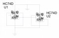
as part of a semester long project I am designing a phase locked loop, which will then be simulated and constructed. I'm having difficulties with the frequency divider, as I don't seem to have enough background knowledge on the implementation of flip flops. I've understood and created the basic layout of a frequency divider (interconnected d flip flops) as shown below. However, ideally the frequency divider should be adjustable. I'm sure this could be achieved using a potentiometer but I'm not sure how to implement this idea. Anything to point me in the right direction would be greatly appreciated!
as part of a semester long project I am designing a phase locked loop, which will then be simulated and constructed. I'm having difficulties with the frequency divider, as I don't seem to have enough background knowledge on the implementation of flip flops. I've understood and created the basic layout of a frequency divider (interconnected d flip flops) as shown below. However, ideally the frequency divider should be adjustable. I'm sure this could be achieved using a potentiometer but I'm not sure how to implement this idea. Anything to point me in the right direction would be greatly appreciated!
Attachments
-
 70.7 KB Views: 17


