Frequency calculations / AAC Tutorial, my numbers are not coming out the same

Thread Starter

Tonyr1084

Joined Sep 24, 2015
7,899
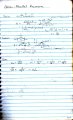
The tutorial on Tank Circuits says to calculate the resonant frequency of a 10µF cap and a 100mH coil you take 1/(2*π*√(LC)), which according to the article says the resonant frequency should be 159.155. Well, I'm coming up with 1591.55. Yes, I know the decimal is in the wrong place, but I'm using Excel to do the calculations. I've tried changing the order of magnitude and go even further away from the AAC answer.

Clarify for me please: 10µF is 0.0001 Farads. Correct?
Clarify for me please: 100mH is 0,1 Henries. Correct?

Isn't micro (µ) smaller than milli (m)?

I only get the right answer when C (10µF) = 0.0001
and H (100mH) = 0.01

That just seems wrong to me.
 

Reloadron

Joined Jan 15, 2015
7,515
Clarify for me please: 10µF is 0.0001 Farads. Correct?
Clarify for me please: 100mH is 0,1 Henries. Correct?
10uF = 0.000010 Farad <this one>
100 mH = 0.100 Henry

Resonant Frequency = 0.0001592 MHz or 159.2 Hz

I believe the capacitance is where there was a problem Tony.

Ron
 
Last edited:

Thread Starter

Tonyr1084

Joined Sep 24, 2015
7,899
@Reloadron Thanks. I could have sworn what you said. But my numbers (in Excel) were not working out. Particularly the C conversion and the H conversion in my program. I was dividing 10(µF) by 1000000 but that was generating the wrong number. When I divide 10µF by 10000000 (100,000,0) an extra zero I'd get the right answer. Same condition existed with the H conversion.

I'm a product of the LAUSD (Los Angeles Unified School District) circa 1960's & 1970's and they were horrible at teaching math. MATH. When it came time for algebra I was skunk lost. The teacher would spout something and then yell "WRITE IT DOWN!" When I'd ask what it means he'd just yell it again. So I'd write something down that I had NO IDEA what I was writing. Might as well have been Chinese or Greek - or any other language I'm not familiar with. So math has held me back.

So now I'm trying to get a handle on these things. As an adult I now know better how to handle the formulas, but it's still like learning a new language - I'm often lost. And when Excel seems to require an extra zero - I'm "Skunk Lost".
 

Thread Starter

Tonyr1084

Joined Sep 24, 2015
7,899
Resonant Frequency = 0.0001592 MHz or 159.2 Hz
Honestly, this one confused me. 0.0001592 MHz, I'm reading as - oh, wait. I think I just got it. 159 hertz is 0.000159 Mega Hertz.

See! I can be slow.

Hey! Thanks for your help.

Thanks all.

Maybe I'm going about it wrong in my Excel spreadsheet. Maybe instead of dividing 10µF I should be multiplying by 0.000001
 

Reloadron

Joined Jan 15, 2015
7,515
So now I'm trying to get a handle on these things. As an adult I now know better how to handle the formulas, but it's still like learning a new language - I'm often lost. And when Excel seems to require an extra zero - I'm "Skunk Lost".
Actually my father referred to math as a language as well as electrical engineering. I was a product of the NYC school system during the 60s. My best learning was in a parochial school during my formative years where things were beat into me, sometimes literally. :)

Ron
 

shortbus

Joined Sep 30, 2009
10,045
I'm a product of the LAUSD (Los Angeles Unified School District) circa 1960's & 1970's and they were horrible at teaching math. MATH. When it came time for algebra I was skunk lost. The teacher would spout something and then yell "WRITE IT DOWN!" When I'd ask what it means he'd just yell it again. So I'd write something down that I had NO IDEA what I was writing. Might as well have been Chinese or Greek - or any other language I'm not familiar with. So math has held me back.
It wasn't only LAUSD, the school system I am from Alliance, Oh, was the same way. The teachers taught to the few "gifted" students and figured the rest of us didn't matter. Again in the 50's and 60's.
 

MrAl

Joined Jun 17, 2014
11,461
Hi,

Note that if L=0.1 and C=0.00001 you get a certain frequency, and if you use L=0.01 and C=0.0001 you get the same frequency. So if you divide one by a number N then if you multiply the other by that same number N then you will get the same frequency.
The difference is the bandwidth changes when we scale the components like that even though the center frequency does not change. This is important because often we need to set the bandwidth or "sharpness" of the network as well as the center frequency.
 

MrAl

Joined Jun 17, 2014
11,461
Hi,

He he :)

As you know, the bandwidth is the difference between the higher 3db down frequency minus the lower 3db down frequency. The center frequency is the frequency of oscillation or the center band pass frequency. That's a total of three frequencies: upper 3db, lower 3db, and center.

So take a simple circuit like an LC in series, and that in series with a load resistor R, and drive the LCR with a sine voltage source, look across R for the output. If we start with an certain L and C, the center frequency is going to be w=1/sqrt(LC) as usual. If we call the lower frequency F1 and the upper F2, then the bandwidth is F2-F1. That's of course provided we see a bandpass response, which is likely. Now if we divide L by 10 we get L/10, and if we multiply C by 10, we get 10*C, and now we have w=sqrt(L/10*C*10)=sqrt(L*C) again. so the center frequency did not change when we scaled L and C by the same factor (one of those factors being the inverse).

The thing that changes though is the sharpness of the response. The center frequency stays the same but the upper and lower F1 and F2 either move closer together or farther apart, depending on if we divide L or multiply L by that factor (and therefore do the opposite to the cap). So we could do L*10 and C/10 and that would give us the opposite shape change than we got with L/10 and C*10. So if we got a sharper response with L/10 and C*10, then we would get a wider bandwidth with L*10 and C/10, and vice versa.
Try it in simulation. BTW keep R constant.

I plotted this a long time ago but i'd have to search for the plots.
Wow, actually found it, but it's smaller than i thought. This was back in the days when we had paper :)
Note this is still subject to review because of it's age, but that's basically how it works. The series circuit plot is an approximation in the first attachment but exact in the second attachment. All the plots are of the magnitude of the impedance.
In the newer plot, R=1 for all three plots.
 

Attachments

Last edited:
Top