Facebook
 Google
 GitHub
 Linkedin
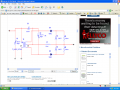
I am curious from this schematic of the foster-seeley detector
here http://www.radio-electronics.com/info/receivers/fm_demod/fm_demodulation.php
half way down the page
I understand how it basically works from the description on the page and from googleing around.
My questions are if I where going to build this FM detector
What values should I make the C's in this schematic?
I am assuming the ones after the diodes should be the same to balance the circuit and give zero voltage at the output when unmodulated (i.e just the carrier exists at the input).
For the diodes I am using either switch or germinum diodes which ever I have this should be to big of an issue since I can always amplify the output however I want...etc I know though germinum forward voltage drop is the lowest and would be a better pick , but what ever....
I am unsure about the resistors R's I would think they should be the same
for balancing reasons...etc but what value I don't know and I don't know if the value matters that much (other then using the same value for both)???
And what value should the RF choke be , and the capacitor that bridges the 2 tank circuits ?
Also
I am assuming the RC circuit has to do with some kind of filter for this detector or something.... maybe this is where the R and C values get defined but I don't even know what the filter is trying to achive...
If I did I would use the formula 1/2*pi*LC in someway to achive a desired cut off frequency....but duno
Thanks for any help on this egar to build/understand this