Exactly, which is why the circuit uses a SCR. Obviously not needed for modern flash systems but since the TS has already wired up the circuit might as well use it.
SG
If the flash is very sensitive then it may work with just a CD4013 flipflop to provide one trigger, and hold the trigger input low until it was manually reset. Ground the clock and data inputs and use the audio trigger circuit to drive the set input high. That will pull the Q output high and the Qbar output low, triggering the flash. That output will remain in the low state until "high" is applied to the reset pin. That is about as simple as I can make it. You will need a 10K resistor from the reset pin to the common circuit.
Evidently this unit is not at all a classic photoflash device with the very simple circuit. And you will need to somehow invert the trigger signal to deliver a high instead of a low. That may or not be simple.
If the flash is very sensitive then it may work with just a CD4013 flipflop to provide one trigger, and hold the trigger input low until it was manually reset. Ground the clock and data inputs and use the audio trigger circuit to drive the set input high. That will pull the Q output high and the Qbar output low, triggering the flash. That output will remain in the low state until "high" is applied to the reset pin. That is about as simple as I can make it. You will need a 10K resistor from the reset pin to the common circuit.
Evidently this unit is not at all a classic photoflash device with the very simple circuit. And you will need to somehow invert the trigger signal to deliver a high instead of a low. That may or not be simple.
It's just needs a switch closure (pulling it's own output to low relative to its own 0V). But as my experiment showed, so long as it is pulled low, it won't recycle, and it won't flash again until you let it float again and it does.
By the way, to be clear, I am not the TS, I was just doing some testing on my own flash from the same manufacturer.
Dear All,
Huge thanks for your help thus far. It really is most encouraging and very appreciated. To answer questions I think I've been asked:
The speedlight/flashgun has an output voltage of approx 5V. All that is needed to fire the flash is something/anything to make closed circuit the two wires in the cable from the flash (a N/O switch).
For my purposes, the delay before any mod can reset needs to be at least 1 second as that is typically how long the shutter is open for (work in the dark, flash creates exposure, shutter speed largely irrelevant).
I may well try more than one of your suggested solutions as electronic components seem really cheap. Feel another hobby coming along
My wife has plans for me tomorrow (trust me there is no such word as retired) so if I don't respond further for a day or so it's because I'm too busy with grandchildren
@gene-stevo Looks like you received plenty of good advice and have some solid approaches to modifying your existing rig.
I wanted to "plant" the notion of moving to an mcu approach. With just a minimum of programming and an inexpensive board, you can create a very flexible platform for operation of a slave flash under a variety of triggers and customizable parameters.
@gene-stevo Looks like you received plenty of good advice and have some solid approaches to modifying your existing rig.
I wanted to "plant" the notion of moving to an mcu approach. With just a minimum of programming and an inexpensive board, you can create a very flexible platform for operation of a slave flash under a variety of triggers and customizable parameters.
Hi Raymond,
Thanks for the nudge towards mcu, I've been thinking about arduino and strawberry pi for a while but wouldn't know where to start as the only coding I know anything about is html and css. Not that good a start.
Regards my photos, I haven't got any using my sound trigger apart from one featuring 4 light bulbs being put to death by air rifle. This at least highlights the issue of multiple firing of the flash. The others, shown in this Facebook album all feature mechanical triggers. Mainly the use of plungers, springs and microswitches with some others making use of fishing line and a weaponized clothes peg
Hi Raymond,
Thanks for the nudge towards mcu, I've been thinking about arduino and strawberry pi for a while but wouldn't know where to start as the only coding I know anything about is html and css. Not that good a start.
Regards my photos, I haven't got any using my sound trigger apart from one featuring 4 light bulbs being put to death by air rifle. This at least highlights the issue of multiple firing of the flash. The others, shown in this Facebook album all feature mechanical triggers. Mainly the use of plungers, springs and microswitches with some others making use of fishing line and a weaponized clothes peg
I think you would pick up some easy programming like Arduino or PICAXE with no trouble - there is simply a ton of help and examples online.
Not only can you integrate a variety of triggers easily, but you have the flexibility of adjusting the delay time between trigger event and flash operation. While I have only limited experience with flash-freeze stuff, I thought that ability to vary that parameter was very helpful.
This mod to the Vellman amp may work depending on the voltage level coming out of the Flash shoe. When the SCR is triggered it will drop the voltage on pin 3,5 of the amp through the diode and discharge C2. This will shut the amp down until C2 recharges which takes about 2 seconds using a 220uf cap.
SG View attachment 170916
Hi sghioto,
Think I'll give your no 13 solution first as that looks the most straightforward, and means the rig will still fit in my existing enclosure.
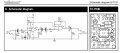
Many thanks BTW for all your effort. Two things though before I order my bits. There appears to be some "mirroring" of components on your schematic compared to the Velleman version. For example the capacitor you want me to swap out for a 220uf is shown as C1 on Velleman sheet. See uploaded file. Second, the voltage from flash is a little over 4V, I'm assuming that's still OK.
Cheers,
Eugene
.
Hi sghioto,
Think I'll give your no 13 solution first as that looks the most straightforward, and means the rig will still fit in my existing enclosure.
Many thanks BTW for all your effort. Two things though before I order my bits. There appears to be some "mirroring" of components on your schematic compared to the Velleman version. For example the capacitor you want me to swap out for a 220uf is shown as C1 on Velleman sheet. See uploaded file. Second, the voltage from flash is a little over 4V, I'm assuming that's still OK.
Cheers,
Eugene
.View attachment 171364

 Facebook
 Google
 GitHub
 Linkedin