yes, I have it. Do you mean I should measure the size of the lug solder to make sure it fits the layout? Please tell me if I misunderstood something. Thank you so much!!hi duy,
I thought you meant the mounting holes for the switch body.
Do you have an actual switch on the bench to check the fit for the terminals?
E
And if it's finished holes, then I will add like 5 - 10 % as ericgibbs says above, but for the drill ones, just keep it, right? Thank you so much!Check with the PCB manufacturer if the specified hole size is the drill size or the finished hole. The finished hole will be narrower than the drill size.
Thank you so much for your advice!!Check with the PCB manufacturer if the specified hole size is the drill size or the finished hole. The finished hole will be narrower than the drill size.
No. You have that wrong.And if it's finished holes, then I will add like 5 - 10 % as ericgibbs says above, but for the drill ones, just keep it, right? Thank you so much!
No. You have that wrong.
If the drill size is specified, the finished hole diameter will be reduced by about 4mil (0.004" or 0.1mm).
You still want to increase the hole size by about 5-10% plus 4mil. For larger components such as connectors and switches I would prefer to have a larger hole than a hole that is too small.
Thank you so much for your advice!Hi,
For a part of that type, I would just double-check the dimensions.
Before laying out my PCB artwork.
E
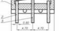
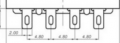
The pins can vary in size.I am drawing a footprint of a 4PDT, the holes are 0.8 x 2.0mm. When I draw the footprint, should I draw the same dimension as the layout (I am scared that the real component might not fit the board), or make it a bit bigger, if so, can you suggest the value I should use? Thank you guys so much.
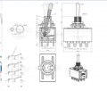
View attachment 309687