fm circuit help

Thread Starter

wenn32

Joined Nov 9, 2010
37
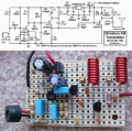
hello i took a picture from Google please see the attachment

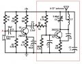
At point 'A' does voltage division takes place??so it means the mic is acting like a variable resistance am i right??

and i couldn't understand the square box area circuit

ok after the R6 resistor we get an AC amplified signal and R7 and R8 are for biasing the Q2 transistor.now if C4 cap is used then wouldn't it ground the AC signal???

after that all the inductance,variable cap i don't get it :-( !!!!!

please help me!
 

Attachments

#12

Joined Nov 30, 2010
18,224
According to Wikipedia, an electret mic is not a variable resistance.
The square box area is the radio frequency section.
C4 grounds signals above a certain frequency.
The variable cap is used to tune the frequency of the oscillator.
 

t_n_k

Joined Mar 6, 2009
5,455
The Electret mic requires some bias voltage to power the integrated internal FET device.

The part in the box is a modulated RF oscillator. The modulation signal comes from the amplified Electret signal. C4 will cause attenuation of the higher frequency components in the audio signal.
 

#12

Joined Nov 30, 2010
18,224
Correcting myself
An electret mic is not a variable resistor, but the capsule of the electret mic contains a fet transistor that acts like a variable resistor.
 

Ron H

Joined Apr 14, 2005
7,063
Correcting myself
An electret mic is not a variable resistor, but the capsule of the electret mic contains a fet transistor that acts like a variable resistor.
The FET is a source follower. It acts more like a moderate impedance voltage source. There is some voltage division due to R1, but it is not intentional. A current source in place of R1 would yield marginally higher signal level.
C4 provides AC grounding for the base of Q2, which is a common base Colpitts oscillator. The oscillation frequency is partly determined by the Q2 collector-base capacitance, which varies as a function of the voltage across it. The audio coupled through C2 and R6 provides the modulation voltage.

EDIT: C4 will cause the audio to roll off starting at about 1.2kHz. It should be changed to 10nF.
 
Last edited:

Audioguru

Joined Dec 20, 2007
11,248
I made that simple circuit 49 years ago.
Its frequency changed all over the place when something moved towards or away from its antenna.
Its frequency changed as the battery voltage ran down.
It sounded awful with no high audio frequencies.
 

Ron H

Joined Apr 14, 2005
7,063
I made that simple circuit 49 years ago.
Its frequency changed all over the place when something moved towards or away from its antenna.
Its frequency changed as the battery voltage ran down.
It sounded awful with no high audio frequencies.
Maybe you can post one of your improved designs.
 

Audioguru

Joined Dec 20, 2007
11,248
Maybe you can post one of your improved designs.
I made this mono FM transmitter about 5.5 years ago and it sounds excellent with a range of over 2km to a sensitive hi-fi or car radio, a range of 300m to a cheap Sony Walkman radio or a range of across the street to a cheap junk FM "scanning radio" from The Dollar Store.

1) It has an RF amplifier to isolate its antenna from the tuned circuit so its oscillator frequency doesn't change when something moves towards or away from its antenna, and increase its range.
2) It has a low dropout voltage regulator so its oscillator frequency doesn't change as the battery voltage runs down.
3) It has pre-emphasis (treble boost) like all FM radio stations have so its audio frequency response is excellent.

It is illegal so I used it only for about 1 hour and I wasn't caught.
 

Attachments

Top