Flip resistance from + to -

Thread Starter

CelestialWanderer

Joined Nov 1, 2024
8
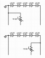
I have a battery/power source that has terminals that are:
+18V
10k thermistor (positive probe here shows +18v when ground probe is grounded)
ground

What components would I use to reverse the polarity of the thermistor reading? So instead it would be:
+18v
10k thermistor (ground probe here shows +18v when positive probe is on +)
ground

Apologies if I'm describing this poorly, or if this has been asked before. I need the voltage to drop at the thermistor terminal as it does with the existing battery. Thanks in advance.
 

BobTPH

Joined Jun 5, 2013
11,516
What is it that you are trying to accomplish that requires this reversal? Perhaps there is a different way.
 

Thread Starter

CelestialWanderer

Joined Nov 1, 2024
8
What is it that you are trying to accomplish that requires this reversal? Perhaps there is a different way.
I'm making a power tool adapter between two brands. One brand of battery is the opposite of the other in terms of how this is handled, with the other terminals being functionally identical.
 

Thread Starter

CelestialWanderer

Joined Nov 1, 2024
8
Your verbal explanation is a bit confusing,
please provide a Schematic-diagram.
This is the best I could come up with since I don't really know what is going on under the hood. I need to make an adapter to connect to the top circuit, so everything together behaves like the bottom circuit. I have no way to change the top circuit.
 

Attachments

Papabravo

Joined Feb 24, 2006
22,082
FYI, Resistance does not have a sign. It is always positive. If it is the voltage drop across the thermistor you want to invert that is a different problem altogether. In order to solve your problem, or for us to help you, drawing complete circuits is a minimum requirement. At least we need to know what the other terminal of the thermistor is connected to. Without that connection there can be no current flow, and by Ohm's Law there can be no voltage drop across the variable resistance.
 

LesJones

Joined Jan 8, 2017
4,511
Are you sure that the thermistors in the two batteries have the same characteristics ? If they don't even swapping the thertmistor to the other side of the battery may not work correctly. (The way its resistance changes with temperature may be different.) If you get the exact thermistor that is in the bottom circuit you could mount it in the adapter in such a way that it was in good thermal contact with the battery pack. The connection to the thermistor in the battery pack would not be used. The themistor in the adapter would connect between the negative and the thermistor connection to the charger.

Les.
 

Thread Starter

CelestialWanderer

Joined Nov 1, 2024
8
Are you sure that the thermistors in the two batteries have the same characteristics ? If they don't even swapping the thertmistor to the other side of the battery may not work correctly. (The way its resistance changes with temperature may be different.) If you get the exact thermistor that is in the bottom circuit you could mount it in the adapter in such a way that it was in good thermal contact with the battery pack. The connection to the thermistor in the battery pack would not be used. The themistor in the adapter would connect between the negative and the thermistor connection to the charger.

Les.
Hi Les,

Thanks for your response! Of course the thermistor will be connected somewhere, in this example the top circuit will connect to my circuit, which will connect to a power tool. The power tool receives power over the thermistor-regulated terminal and will shut off if the battery gets too hot.
 

Alec_t

Joined Sep 17, 2013
15,119
Of course the thermistor will be connected somewhere, in this example the top circuit will connect to my circuit, which will connect to a power tool.
But the way the power tool detects the thermistor's resistance value is an unknown. It may apply some voltage to the thermistor terminal and measure current, for example, or may use some other way. An adapter would have to take that into account.
 

BobTPH

Joined Jun 5, 2013
11,516
If you cannot get inside the battery pack, this is not at all easy. Best I can think of is an interposed circuit that measures the resistance then connects a digital potentiometer that duplicates the resistance connected in the right posotion.

The electronics is fairly easy for a skilled hobbyist. The mechanics of this is more of a challenge (to me at least.) The adapter would need to go between the tool and the battery pack and be robust enough to hold the battery firmly while the tool was in use.

A thought: if you don't mind a power cord between the battery and the tool, they could be separated, making the mechanical design simpler.
 

MrChips

Joined Oct 2, 2009
34,817
Your power tool and battery charger would be monitoring the battery temperature based on a circuit such as this.

Battery temperature monitor.jpg

As the temperature rises, the resistance of an ntc thermistor will fall. The sensed voltage will rise.
When the voltage exceeds a set reference voltage, the comparator will send an output signal to turn off the tool or charger.

What you need is a circuit that will reproduce the rising voltage as the temperature rises.
This circuit takes the falling voltage and inverts it to a rising voltage.
I cannot specify circuit values without knowing the requirements of the existing circuits.

Battery temperature monitor (2).jpg
 

MisterBill2

Joined Jan 23, 2018
27,524
I suggest disconnecting it completely for the one it does not match.

But what I see as quite amazing is tow different companies using the same connection mechanical design. Usually every one works hard to be non-compatible with all the others. At least that is my experience.
 

AnalogKid

Joined Aug 1, 2013
12,132
This is going to harder than you think, because of the circuit inside the charger. It almost certainly has a fixed resistor from the thermistor terminal to either +18 or GND, depending on which model. That forms a 2-resistor voltage divider whose central node voltage goes off to whatever is monitoring battery temperature. Without knowing the voltage range that the monitor expects from the thermistor divider, simulating it with an opamp will be tough.

ak
 

MisterBill2

Joined Jan 23, 2018
27,524
The simple way would be to fake it by using an external temp sensor as part of the charger and not using that terminal. Not really very simple, though.
 
Top