Fixing Acrade Basketball IR Scoring Mechanism

cmartinez

Joined Jan 17, 2007
8,814
Voltmeter arrived today! I'm at work now but I'm sure I'll be back with questions once I get it fired up. So as I understand it I would want to set it to continuity test and touch both ends of each wire to ensure the current goes through them? Should I also plug the system in and check for power coming from the wires that go to the emitters? ...and if so what setting would I use for that? Thanks!!!
Excellent... Set your voltmeter to read DC and test both wires reaching the IR emitters. Then test for continuity on each extreme of each wire. Most MMs (multimeters) have a buzzer function for continuity testing.
 

Thread Starter

myersgg

Joined Dec 30, 2014
10
OK before I take too much apart, can you tell me what setting I would set (if any) to test the ends in the attached image? I've disconnected the plug going from the scoreboard to the IR emitters (see attached image). Each side of the hoop has 4 wires that go to them (from the plug on the left), and actually as seen in the earlier post I guess there's really 2 IR emitters per side with 2 wires going to each emitter most likely. Since none of the IR emitters are lighting up my guess is they aren't getting power (which would come from the plug on the right side of the image. Am I able to use the voltmeter to test each of the ports to see if they are giving power and what setting would I use for that? Thanks and sorry for being so incompetent with this!!
 

Attachments

cmartinez

Joined Jan 17, 2007
8,814
OK before I take too much apart, can you tell me what setting I would set (if any) to test the ends in the attached image? I've disconnected the plug going from the scoreboard to the IR emitters (see attached image). Each side of the hoop has 4 wires that go to them (from the plug on the left), and actually as seen in the earlier post I guess there's really 2 IR emitters per side with 2 wires going to each emitter most likely. Since none of the IR emitters are lighting up my guess is they aren't getting power (which would come from the plug on the right side of the image. Am I able to use the voltmeter to test each of the ports to see if they are giving power and what setting would I use for that? Thanks and sorry for being so incompetent with this!!
Can you post a pic of your brand-new-out-of-the-box-with-a-new-car-smell :cool: voltmeter?
 

cmartinez

Joined Jan 17, 2007
8,814
Turn your voltmeter dial to the red area (DC) and plug the black probe into the black receptacle, and the red probe into the red receptacle on the right.
If I were you, I'd reconnect the the plugs in your game, and test the two wires of each emitter (we'll leave the receivers alone for now) attached directly on them, or as close as possible, see if there is any power reaching them. If not power is reaching them, then I'd test the same two wires at the point where they're attached to the main board, if you get a positive power reading, then it means that the wires are broken at some point, if there is still no power, we'd need to take a closer look at that board's circuit so as to start testing other areas.
 

Thread Starter

myersgg

Joined Dec 30, 2014
10
OK will do, do I shouldn't test anything with these plugs? These are the easiest to access which is why I was hoping I could begin testing there before pulling apart the other components haha
 

cmartinez

Joined Jan 17, 2007
8,814
OK will do, do I shouldn't test anything with these plugs? These are the easiest to access which is why I was hoping I could begin testing there before pulling apart the other components haha
What you need to do, is make sure that voltage is reaching the emitters, the closer to the emitters you place the probes, the better. After that, check for voltage at the main board.
 

Thread Starter

myersgg

Joined Dec 30, 2014
10
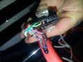
OK before I do anything too crazy, here is an image of one of the emitters. Would you recommend stripping some of the wire for each side and placing a probe on each wire or doing something else? Also, when I turn that voltmeter to the DC area with the probes plugged into the locations as mentioned (but the prob ends not touching anything) the reading jumps around pretty wildly, is that normal? I guess I expected it to read 0 until I placed the probes on something...but also I'm new to this :). Thanks for your help!!!
 

Attachments

cmartinez

Joined Jan 17, 2007
8,814
OK before I do anything too crazy, here is an image of one of the emitters. Would you recommend stripping some of the wire for each side and placing a probe on each wire or doing something else? Also, when I turn that voltmeter to the DC area with the probes plugged into the locations as mentioned (but the prob ends not touching anything) the reading jumps around pretty wildly, is that normal? I guess I expected it to read 0 until I placed the probes on something...but also I'm new to this :). Thanks for your help!!!
Those wires look rather thick for that kind of sensor, so no, I don't think it's necessary to strip them since I doubt they're broke at any point. Just follow those wires downstream from the sensor and see if you can connect the probes in already exposed areas of the wire, perhaps at the point where they go into the connector. And yes, it is normal for the display to be unstable while the probes are floating (not connected to anything). As a simple test, you could turn on your voltmeter, turn the dial to DC, and then just connect the probes together (short circuit them)... your voltmeter's display should stabilize and read 0V
 

Thread Starter

myersgg

Joined Dec 30, 2014
10
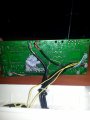
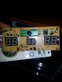
I took a big step and took off the entire scoring mechanism/circuit board. The two sets of wires at the top of the image connect to the scoring mechanism (one of each side of the hoop). What should I check next? I've included a picture of the circuit board (and also a front pic if that helps).

Thanks so much!!!!
 

Attachments

Top