Fixing a dead amplifier - Phoenix Gold MS250, 1990 vintage

SoftwareGuy

Joined Oct 29, 2013
29
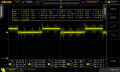
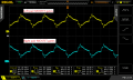
It looks like I have great output from the SG2525, here are output pins A and B:
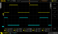
SG2525_output_a-and-b.png

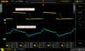
On the MOSFET gates I do have some part of a square wave, on top of about +13V DC bias. Q9 has much more amplitude than the other 3, I'm not sure how to interpret that. Should I expect better square waves on the gates than this, and is the +13V DC bias on the gates expected? Here are the readings in the order (left to right) Q10, Q9, Q8, Q7:
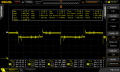
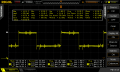
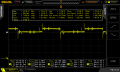
Q10.png Q9.png Q8.png Q7.png
 

Attachments

Thread Starter

MrSoftware

Joined Oct 29, 2013
2,273
Ok looking at this closer, I'm confused by something. These are npn MOSFETs, the gate never drops below 12.6v, shouldn't they be "on" continuously?

Also looking at the sg2525 output, the Vpp is about 13.5v with a peak around 14v, and it drops down to about .5v at the lowest. The square wave on the MOSFET gates also peaks near 14v, but it doesn't drop down below about 12.6v. Something is holding it high. Is this a useful clue about which device might be at fault? I guess I need to do what you said and find the device that is adding the positive bias to the sg2525 output, effectively messing up the square wave.
 

Lestraveled

Joined May 19, 2014
1,946
Damn, your right. I assumed from the part number that there were P channel fets, but they are N (enhancement) fets. ..........How good are your de-soldering skills??
 

Dodgydave

Joined Jun 22, 2012
11,395
Find which terminal the CT on pulse transformer is connected to, positive or negative supply, that will show if the fets are pulsed high or low, judging by the hexfets which are N type, i would say pulsed low with the CT at +12v, so if the resistors are hot one side must be pulled low for some reason. What happens if you disconnect the gates on the fets?
 
Last edited:

SoftwareGuy

Joined Oct 29, 2013
29
@Lestraveled - I'm pretty confident with my soldering, should I remove one of these FETs? I just picked up a new spool of copper braid too..

@Dodgydave - The CT is common with the chassis, AC and HV on the transformer, and one side of the rectifier diodes, but there is no continuity between CT and any of the FET pins or the negative on the main supply connector (Battery -).

The "Drive" leads from the transformer show continuity with the main positive source connector (Battery +), as well as with the the FET drains _and_ the FET gates. Going on the behavior of my meter, it seems that "Drive" is connected to the FET source pins via a capacitor.

The resistance between 3 of the FET gates and their respective drains is about 2ohm, but the fourth FET shows about 9ohm between gate and drain. Is this significant?

What I'm confused about, is with 12v+ on the gates and drains, and 0v on the source, how come the FETs aren't conducting?

Side note: the other thread was intended to be a generic help me understand SWPS thread, it wasn't intended to be about fixing this specific amplifier. :)
 

Dodgydave

Joined Jun 22, 2012
11,395
Ok, sounds like the ct is for the HV side using +/_ diodes for the amplifier ht, are there 7 terminals on the transformer, 3 on the secondary side 4 on the primary, check continuity from the fet drains to the transformer, that should give you the primary side.
 

Thread Starter

MrSoftware

Joined Oct 29, 2013
2,273
@Lestraveled - OK thanks for the help so far, hold on tight! ;)

@Dodgydave - There are 9 total leads from the transformer. The 4 labeled "Drive" and "+" have continuity with the positive voltage source (battery +), and with the drain and gate on the MOSFETs. So this must be the primary.

The other 5 transformer leads, labeled CT, HV and AC have continuity with each other and one pin of the diodes (and with the amplifier chassis), this must be the secondaries.

The FET source pins have continuity to the negative supply (battery -).
 

Dodgydave

Joined Jun 22, 2012
11,395
I would disconnect the primary sides and measure the fets for shorts d/s and s/g, you may get false readings with the fets still in circuit, also see which primary coil goes to which fet, it may be the fets are in parallel, i think the there are two primary coils connected in series to make a centre tap, or they could be wired as two separate pulsed coils with the capacitors making a centre tap.
 

Thread Starter

MrSoftware

Joined Oct 29, 2013
2,273
OK, if I understand correctly, I'll remove the primaries and check out the FETs. If it looks like they are in parallel then I'll remove them and check them out individually.

Just for my knowledge; with the Vgs being +12V, and Vds being +12V, assuming they're not bad wouldn't they be conducting?
 

Dodgydave

Joined Jun 22, 2012
11,395
If the vds is +12v, dont see how its working, if its pulsing i would expect an ac signal there, as for the Hot resistors they may the Source current monitor, so if the fets are hard on, they will be hot.
 

Thread Starter

MrSoftware

Joined Oct 29, 2013
2,273
I disconnected the primaries on the transformer and checked out the FETs, they are in pairs. The left two gates and drains are in parallel, and the right two gates and drains are in parallel. All four source pins are in parallel. Of those 4 resistors that get hot, the left two are connected to the left two FET gates, and the right two connect to the right two FET gates. With the scope on it (everything assembled) I can see that the signal to the left two FETs are 180 degrees out of phase with the right two FETs. The 4 primary leads on the transformer are connected to the PCB in 3 locations; two of the primary leads are connected together.

Is my next step to remove the FETs and check them individually? I'm not understanding why it's only drawing less than 1A idle current when it seems that all 4 of these FETs should be "on", essentially shorting the input power.

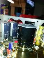
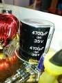
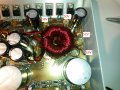
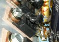
Also I noticed that the two largest caps seem to have expanded in length, stretching the plastic around them. See the attached images, compare to the caps in the background. I didn't think about caps being the problem because of how it just stopped, but could this be it?

20151012_091357.jpg 20151012_091421.jpg
 

Dodgydave

Joined Jun 22, 2012
11,395
Then its a centre tapped primary, like figure 10 in datasheet, with complimentary push pull fets, either the fets have blown, the resistors are too high value due to heat, or back emf diodes blown,

If the signals are on the fet gates 180 out of phase with each other, the sg chip looks ok, it could be the secondary side pulling it down, it maybe worth disconnecting the secondary sides,reconnect the primary sides..see if it gives out ac on the scope.

The caps that you mentioned, are they on the primary or secondary side?
 

Thread Starter

MrSoftware

Joined Oct 29, 2013
2,273
First, thanks again for your continued help and time, I really appreciate it!

I will try your suggestion with the secondaries and report back what I find.

I'm not sure which side the caps are on, but I'll try to figure it out.

Is it possible they configured it like figure 9, except used MOSFETs instead of BJTs? I only ask because I see resistors and caps next to the sg2525 as shown in figure 9, but figure 9 definitely doesn't show a MOSFET...
 

Dodgydave

Joined Jun 22, 2012
11,395
Yes its can be either fig 9 or 10, using mosfets you dont need gate drive resistors, but they may have designed it better with gate drive resistors,
 

Thread Starter

MrSoftware

Joined Oct 29, 2013
2,273
I'm almost positive the pair of large caps (4700mfd) are on the secondaries, as are the pair of 470mfd caps near by. I put my capacitance meter across the diode pins and the left two diodes each gave me about 4900mfd, and the right two diodes gave me 5100mfd. So I think the diodes are in pairs, each diode pair gets one big and one small cap.

I think I found something significant; The diodes are mounted on insulators, separating them from the amp chassis. I put my capacitance meter across the diode bodies and the amp chassis, and the left two diodes gave me about 5000mfd, the right two diodes gave me nothing. It turns out, the right two diode bodies are shorted to the amp chassis. This doesn't seem right since they are mounted on insulator pads, what do you think? Maybe something in circuit with the diodes has gone bad and shorted to the chassis?

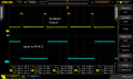
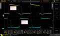
With the secondaries disconnected, things looked quite a bit different on the primary side. There was 18Vpp AC on the gates but with about +10V DC bias. So I guess it's really DC, but with a lot of variance. The drains had identical signals to the gates. Here's what the scope showed on the gates:

gate-inputs_left-pair_right-pair.png

The SG2525 output had some more noise in the signal, but was otherwise similar. Here is the SG2525 output signal compared to the signal on the MOSFET gates:

sg2525-output_gate-input.png

Here's the SG2525 output A and B, with the secondaries on the transformer disconnected.
sg2525_outputs_A-and-B.png
 

Dodgydave

Joined Jun 22, 2012
11,395
Disconnect the secondary sides and look at the secondary coils with the scope and see what voltage is there, if its about 30 to 40 volts its ok, then there is something on the secondary side thats gone, maybe the diodes or caps have blown too.
 
Last edited:

Thread Starter

MrSoftware

Joined Oct 29, 2013
2,273
Voltage on the disconnected secondaries is pretty high. There are 5 secondary leads, the voltages relative my power supply ground (peak-peak) were 38V, 50V, 52V, 63V and 6V. That low one must be a center tap? The 38V/52V pair were 180 degrees out of phase with the 50V/63V pair. The 6V lead is in-phase with the 50V/63V pair. Here's an image with the voltages on it:

secondary_voltages_disconnectedb.jpg

So it sounds like something downstream of the secondaries is dead. Getting warmer! :) What should I look for next? I'm tempted to replace those big caps..

The diodes have something attached to them and I'm not sure the purpose. It looks like a cap and a resister sealed together. Here's a picture:

diodes-b.jpg

Is this to filter noise?
 

Dodgydave

Joined Jun 22, 2012
11,395
Only way to solve this is to connect the secondary sides,in pairs, then check for output voltage in DC, anything after the diodes can be disconnected, to isolate the circuit, your going to have to draw the secondary sides out to see how the dc feeds are arranged, my bet is a centre tapped with two sets of secondaries, one giving +/- 35v, the other +/- 45v,

I would connect the 35v sides up first, the check for dc, if ok connect the 50v up and re check, one of the ht rails is pulling it down, it could be the caps or output transistors on the audio amp.
 
Top