Facebook
 Google
 GitHub
 Linkedin
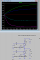
I’m seeking help troubleshooting my dead Phoenix Gold MS250 amplifier, an early 1990’s vintage. It served me well for many years, then one day I’m driving along listening at low volume and it just stopped. No pop, no click, no smoke.. just as if it was turned off. And hasn’t given me any output since.
Now I get a green power light, but absolutely nothing on the outputs. No click or pop when it turns on or off, not even a blip on the scope. Feeding it with a 1kHz 1Vpp sine wave input (gain in the center) also yields no output (see scope screen below). The manual claims 2A idle current @14v, I measure only .36A idle current @14v input. After several minutes powered up, ambient temp 74F, the SG2525A PWM chip is slightly warm at about 80F, but the 4 bluish resistors just above it, with a cap between them (R9, R10, R11, R12) are HOT at 155F. The caps are all cool and I didn’t notice any other hot spots on the board.
Does anyone have suggestions on where to go from here? I thought I would dig up the data sheet for the SG2525A chip and see if it’s giving any PWM output, but I’m certainly open to any and all suggestions.
The best I could do for a schematic was an unofficial MS275 schematic. I’m told the MS250 and MS275 were nearly identical, but I don't see some of the key IC's on the schematic so I'm not sure how helpful it is... I’ve added a link to the manual and some pictures below. If you click for full screen images, you'll get the high resolution versions.
Owners Manual:
https://drive.google.com/file/d/0B7i1pd8bSu5oQlFId1VsLWhYNTQ/view?usp=sharing
Schematic (unofficial):
https://drive.google.com/file/d/0B7i1pd8bSu5ocU1SWG9HckRkV1U/view?usp=sharing
Input and output:

Hot resistors marked:

Various pics:


Now I get a green power light, but absolutely nothing on the outputs. No click or pop when it turns on or off, not even a blip on the scope. Feeding it with a 1kHz 1Vpp sine wave input (gain in the center) also yields no output (see scope screen below). The manual claims 2A idle current @14v, I measure only .36A idle current @14v input. After several minutes powered up, ambient temp 74F, the SG2525A PWM chip is slightly warm at about 80F, but the 4 bluish resistors just above it, with a cap between them (R9, R10, R11, R12) are HOT at 155F. The caps are all cool and I didn’t notice any other hot spots on the board.
Does anyone have suggestions on where to go from here? I thought I would dig up the data sheet for the SG2525A chip and see if it’s giving any PWM output, but I’m certainly open to any and all suggestions.
The best I could do for a schematic was an unofficial MS275 schematic. I’m told the MS250 and MS275 were nearly identical, but I don't see some of the key IC's on the schematic so I'm not sure how helpful it is... I’ve added a link to the manual and some pictures below. If you click for full screen images, you'll get the high resolution versions.
Owners Manual:
https://drive.google.com/file/d/0B7i1pd8bSu5oQlFId1VsLWhYNTQ/view?usp=sharing
Schematic (unofficial):
https://drive.google.com/file/d/0B7i1pd8bSu5ocU1SWG9HckRkV1U/view?usp=sharing
Input and output:
Hot resistors marked:
Various pics:
Last edited: