FIR FILTER

Ian0

Joined Aug 7, 2020
9,671
What is the ADC,
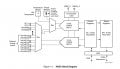
Due to the high sampling rate, it sounds like a sigma delta convertor ,
I'm using some LPC microcontrollers which can do 1Msample/second, and they are SARs. The sigma-deltas that I have come across have huge resolution but at very low sampling rates (24 bit @ 15 samples/second, for instance)
 

Ian0

Joined Aug 7, 2020
9,671
it's name is xadc, and it is the internal adc of the zynq XA7Z030. Now I'm going to check on the datasheet and see if it says the type of adc
It doesn't say - but I expect it to be an SAR.
It does say that it has a selectable internal or external reference. What happens if you select the internal reference?
It also says that the external reference can be used for lots of other things. I haven't got the full datasheet - is it overloading the external reference?
 

Thread Starter

Lorenzo Ruscitti

Joined Nov 12, 2018
35
It doesn't say - but I expect it to be an SAR.
It does say that it has a selectable internal or external reference. What happens if you select the internal reference?
It also says that the external reference can be used for lots of other things. I haven't got the full datasheet - is it overloading the external reference?
ok i'll check

Returning to the original question:

Does it make sense here to apply a fir filter on the discrete exits from the ADC?

I ask myself this question because usually when the entity filters fir I knew of the wave entering the ADC and therefore I knew both frequency and amplitude.

In this case, however, since the temperature monitoring is all internally not as is the analog signal that can come and also does not estimate the disturbance that is generated inside the xadc.

What I do know is that the temperature monitoring happens across a diode probably.
 
Last edited:

Deleted member 115935

Joined Dec 31, 1969
0
it's name is xadc, and it is the internal adc of the zynq XA7Z030. Now I'm going to check on the datasheet and see if it says the type of adc
Ok, its the internal ADC in the Xilxin chip ,
used to measure the chips temperature and base supply voltages,

The chip itself has an internal 1.25 Vref
why re you supplying an external Vref,
it sounds like the internal Vref is better than your external one,

I'm still having problem with the temperature of the external ref your measuring,

what temperature is the silicon on the Xilinx chip reporting ?
 

Deleted member 115935

Joined Dec 31, 1969
0
Do you have the ADC averaging turned on or off ?

Sorry, but the little bits of information you are giving us, are not making a coherent story,

Can you post the schematic of the adc input circuit and the vref you have provided to the Xilinx chip,

So you say you have done a test, at temperature and it fails when its hot.

you need to workout what is causing the fail,
not mask the effects


Can you explain the test you have done,

is the unit in a environmental chamber ?
what temperature have you set the chamber to , is the temperature constant or cycling, what period over what range

The temperatures you mention, where and how are you measuring this ,
is it the Xilinx internal temperature, or external / alternate measurements,
is it a spot thermometer ?

What does the PSU to the vref look like over temperature,
what does the Vcc noise to the XADC rails look like over temperature,


Bottom line
this "waveform" is not how the gear is meant to work in normal times,
so you are doing something thats "unusual"
unless you identify what that unusual is,
then the fault will come back and bite you hard later.

Only once you know the cause, can you think of a fix,
else you are putting a patch on it, that is liable to break
 

Thread Starter

Lorenzo Ruscitti

Joined Nov 12, 2018
35
Ok, its the internal ADC in the Xilxin chip ,
used to measure the chips temperature and base supply voltages,

The chip itself has an internal 1.25 Vref
why re you supplying an external Vref,
it sounds like the internal Vref is better than your external one,

I'm still having problem with the temperature of the external ref your measuring,

what temperature is the silicon on the Xilinx chip reporting ?
As I said earlier, I didn't do the HO and consequently it can't be touched.
On the CAN when the ripple problem occurs on the reference output I have:
Treference = 92 °
Tcore = 108 °

but a heatsink is mounted on the zynq
 

Deleted member 115935

Joined Dec 31, 1969
0
We need to see and understand your problem , else we can not give an informed decision

"doctor, I feel sick, but I will not let you examine me, but it happens in the morning"


CAN is a communication protocol, so it can not have a temperature,
where are these temperatures being measured ?

is the Xilixn chip an automotive qualified part ?
if not, and that 108 is from the internal Xilinx chip temperature sensor, then your out of range, and all bets are off.


Please, can you answer the questions , and we can help you.
 

Thread Starter

Lorenzo Ruscitti

Joined Nov 12, 2018
35
We need to see and understand your problem , else we can not give an informed decision

"doctor, I feel sick, but I will not let you examine me, but it happens in the morning"


CAN is a communication protocol, so it can not have a temperature,
where are these temperatures being measured ?

is the Xilixn chip an automotive qualified part ?
if not, and that 108 is from the internal Xilinx chip temperature sensor, then your out of range, and all bets are off.


Please, can you answer the questions , and we can help you.
As I said in the previous messages.

I on the CAN only send us the temperature value which is calculated daily by the zynq chip.

108 ° is the temperature calculated by zynq and reintroduces the acceptance range because the maximum is 125 °.

The problem is NOT the zynq but the chip that generates the reference.

I understand and agree with you that you can use the internal reference but this excludes it because it is not possible to implement it.

I understand all the reflections but I am not what I am looking for at the moment because I have no freedom of action.

The only thing I can do at the moment is to try to see if it is feasible to insert a filter, made in C code on the samples acquired by the xadc.

I'm doing tests in the climatic chamber.

25min at 25 °
10min 70 °
10min 75 °
from here I proceed in steps of 5 degrees to try to replicate the problem.

To monitor the temperature of the chip that generates the reference I have a thermocouple connected to it.
 

Ian0

Joined Aug 7, 2020
9,671
First, as you can't modify the hardware to include an antialiasing filter, you would have to increase the sample rate from 10 samples/second to >20,000 samples/second, otherwise the 10kHz signal would present itself as an alias, and be very difficult to remove. Then it could possibly be IIR filtered. If you wanted to reduce the bandwith back down to 10Hz, a FIR would need 2000 stages.
Even if that is successful, are you certain that the superimposed 10kHz waveform has not reduced the DC accuracy of the reference?
 

Thread Starter

Lorenzo Ruscitti

Joined Nov 12, 2018
35
First, as you can't modify the hardware to include an antialiasing filter, you would have to increase the sample rate from 10 samples/second to >20,000 samples/second, otherwise the 10kHz signal would present itself as an alias, and be very difficult to remove. Then it could possibly be IIR filtered. If you wanted to reduce the bandwith back down to 10Hz, a FIR would need 2000 stages.
Even if that is successful, are you certain that the superimposed 10kHz waveform has not reduced the DC accuracy of the reference?
Quite right, excellent observations.

First of all I increase the reading time of the task that instead of reading every 100 ms I make it read more frequently, because then I have to be careful not to change the task scheduling too much. I say this because if the task goes into the active state more frequently it could affect the execution of other tasks, but this is another problem.

I have the 10khz disturbance on the reference, you say that I can consider it as if it were also svrapposto to the outgoing decree samples?

As per attachment I have 1Msps but since I am more line the 1 Msps value I have to divide it by the number of lines so I can actually know the sampling frequency used for each line?

Thank you
 

Attachments

Deleted member 115935

Joined Dec 31, 1969
0
As I said in the previous messages.

I on the CAN only send us the temperature value which is calculated daily by the zynq chip.

108 ° is the temperature calculated by zynq and reintroduces the acceptance range because the maximum is 125 °.

The problem is NOT the zynq but the chip that generates the reference.

I understand and agree with you that you can use the internal reference but this excludes it because it is not possible to implement it.

I understand all the reflections but I am not what I am looking for at the moment because I have no freedom of action.

The only thing I can do at the moment is to try to see if it is feasible to insert a filter, made in C code on the samples acquired by the xadc.

I'm doing tests in the climatic chamber.

25min at 25 °
10min 70 °
10min 75 °
from here I proceed in steps of 5 degrees to try to replicate the problem.

To monitor the temperature of the chip that generates the reference I have a thermocouple connected to it.
Ok, your the expert,

the XADC has the option to average a power of two samples to give on output,
which is a simple low pass filter,

good luck
 

Thread Starter

Lorenzo Ruscitti

Joined Nov 12, 2018
35
Hello

i solved it with a moving average filter.
Today I am doing other tests to estimate the measurement tolerance during filtering when the ripple occurs.
 

Ian0

Joined Aug 7, 2020
9,671
Hello

i solved it with a moving average filter.
Today I am doing other tests to estimate the measurement tolerance during filtering when the ripple occurs.
"Solved" isn't the word I would have used.
Does the DC level for the reference still meet spec? Is it better than the internal reference?
 

Thread Starter

Lorenzo Ruscitti

Joined Nov 12, 2018
35
First, as you can't modify the hardware to include an antialiasing filter, you would have to increase the sample rate from 10 samples/second to >20,000 samples/second, otherwise the 10kHz signal would present itself as an alias, and be very difficult to remove. Then it could possibly be IIR filtered. If you wanted to reduce the bandwith back down to 10Hz, a FIR would need 2000 stages.
Even if that is successful, are you certain that the superimposed 10kHz waveform has not reduced the DC accuracy of the reference?
Can you explain this part to me better?

For now the reference situation has not changed, I tried to propose the internal reference but it was rejected.

Thank you
 
Top