Fine tune from additional variable capacitor

Thread Starter

DaniKowa

Joined Sep 23, 2020
218
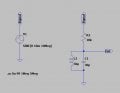
Hi guys! This simulation is a very simple and ancient tuning circuit. C1 is to be considered variable and by varying its value it causes the tuning frequency to vary. The question is: I would like to make the tuning be finer. I could probably add an additional capacitor in parallel to C1 with a smaller value for fine tuning but I lose some of the high band. Is there a better way to do this? Thank's
 

Attachments

MisterBill2

Joined Jan 23, 2018
18,171
Yes, there does exist a simple solution. But first you must choose the frequency range that you want for the resonant circuit. Then, after choosing the inductance, you can calculate the required capacitance for resonance at the frequency extremes you set. Then select capacitors so that the range of the variable capacitance plus the value of the fixed capacitance allows the desired range of variability.
It is entirely possible to select values that can not work in a real circuit. That usually means to guess again.
 

Jerry-Hat-Trick

Joined Aug 31, 2022
545
My (albeit limited) experience of small value variable capacitors is that they difficult to fine adjust anyway. So if you want to put a small variable capacitor in parallel maybe consider a fixed value a bit higher than that in series with a variable capacitor of maybe an order of magnitude higher which turns cleanly. It won't be linear, but the overall capacitance is easier to control
 

MisterBill2

Joined Jan 23, 2018
18,171
OK, evidently an explanation is required for the word "trimmer", and while I am at it, also the word "padder", as they apply to variable capacitors, as the implication is not intuitive.
A TRIMMER capacitor is in series connected to the primary adjustable capacitor a d it "trims" the maximum available capacitance of the combination when the primary adjustable capacitor is at it's maximum capacitance setting. The "PADDER" capacitor is connected across the primary adjustable capacitor, and is used to set the minimum capacitance when the primary adjustable capacitor is at it's minimum capacitance setting. Mostly trimmers and padders are used in applications where there is a multi-section main variable and more than one tuned circuit must be set to a particular resonant frequency at the same time.
The two terms are sometimes used incorrectly to describe small variable capacitors in general.
 

Jerry-Hat-Trick

Joined Aug 31, 2022
545
Try the following:
Or maybe:
1665747157413.jpeg
The point being, with C1 variable you have course adjustment and the parallel arm with C2 (same component as C1) in series with C3 can never increase the capacitance more than the value of C3. Not linear, but allows C2 to fine tune. Not sure how RF will respond to this as my logic is fairly simplistic, but maybe worth a try? The lower the value of C3 (fixed) the finer the tuning adjustment)
 

Tonyr1084

Joined Sep 24, 2015
7,852
Forgive me if this is ignorant, but when you parallel capacitors you increase overall capacitance? Adding a second parallel cap to an existing cap will increase the farad rating. You would need to lower the existing cap by some measure and add a variable of some measure to achieve the desired capacitance. At least that's how I understand it.
 

MisterBill2

Joined Jan 23, 2018
18,171
Forgive me if this is ignorant, but when you parallel capacitors you increase overall capacitance? Adding a second parallel cap to an existing cap will increase the farad rating. You would need to lower the existing cap by some measure and add a variable of some measure to achieve the desired capacitance. At least that's how I understand it.
Tes, capacitors in parallel add, but look at the numbers, OK??
 
when you parallel capacitors you increase overall capacitance? Adding a second parallel cap to an existing cap will increase the farad rating. You would need to lower the existing cap by some measure and add a variable of some measure to achieve the desired capacitance. At least that's how I understand it.
That's why I reduced variable C1 from 30p to 25p and then added the leg in parallel with fixed C3 = 5p and variable C2 = 25p which, even with C2 set at 25p the combination is actually just a little less than 30p. Turning C2 from end to end actually adjusts the overall capacitance by a little less than 5p
 

Tonyr1084

Joined Sep 24, 2015
7,852
I feel like you're talking down to me. Again, forgive my ignorance.

I saw the change in the numbers. Resistors in parallel, that I understand. Caps in parallel, a little scary for me. I'm way down on the evolutionary scale of knowledge about electronics. I'll speak boldly about things I know, softly about things I'm a little unsure of. I'll shut my mouth when I just don't know. I still make mistakes. Forgive me. "OK??"
 
I feel like you're talking down to me. Again, forgive my ignorance.

I saw the change in the numbers. Resistors in parallel, that I understand. Caps in parallel, a little scary for me. I'll speak boldly about things I know, softly about things I'm a little unsure of. I'll shut my mouth when I just don't know. I still make mistakes.
Hey, please don't take it personally - either from me or anyone else. I've not been a member for long but I've already made quite a few mistakes - either people ignore me or point out, with varying degrees of civility, the error of my ways. So please don't keep quiet if you are not sure or don't know. I've also learnt a great many new things. Not a bad idea to cushion posts by saying you are not sure, or even specifically asking for clarification but as far as I'm concerned your question about my post was perfectly legitimate and gave me the chance to clarify!

One way to get your head around capacitors (or Leydan Jars as they were and should be called LOL) is to think of how they were originally made - two parallel plates separated by an insulator. The bigger the area of the parallel plates the bigger the capacitance, the closer the plates are together, the bigger the capacitance.

Now consider two equal capacitors in parallel - you've simply increased the capacitance because you've doubled the area so you've doubled the capacitance. Now put them in series - the two "plates" where they join make no difference, you've simply doubled the distance apart, so you've halved the capacitance. If you think of capacitance as being an impedance equal to 1/C the same formulae for capacitors can be used for series and parallel resistors!

At least I think that's right.... OK? :D
 

DickCappels

Joined Aug 21, 2008
10,153
There was a time when special capacitors were made to be used for vernier tuning like this one that could be adjusted by a panel mounted dial. They are probably still made for some applications but it is unlikely to show up in the average home or office these days.

1665848110318.png

Above Jackson Brothers 6 pf to 12 pf vernier tuning capacitor.

Notice that the shaft is geared way down so you can finely adjust the tuning. These were usually used across the main tuning capacitor in the manner you described, which had a much wider tuning range.
 

atferrari

Joined Jan 6, 2004
4,764
Well before building my first valves XMTR (CW modified for AM - 80 / 40 m bands) I started collecting whatever I could salvage. Still recall the many ganged variable capacitors I got similar to this:

Ganged var air cap.png

For receivers, I learnt then that the "trimmers", small ones (one per section) were in parallel and the alignment of the IF strip required them adjusted in orderly sequence. I vaguely recall disassembling one trimmer where the dielectric, IIRC was kind of a thin piece of mylar or similar.

I inherited a Scott CW receiver (from the WWII era) which had on the panel the BFO control knob (Beat frequency oscillator control).
The knob commanded the shaft of a very small capacitor (quite similar as described by @DickCappels ) to adjust that BFO. Used it jointly with my transmitter. Happy times.
 

MisterBill2

Joined Jan 23, 2018
18,171
The funny thing about the small adjustable capacitors along the side of the main tuning capacitor is that while everybody, including me, calls them trimmers, they are actually padder capacitors, as they are in parallel with the main capacitor and pad the main capacitance in all positions, equally..
and the insulation material was probably mica, that was the very most common. It would not be damaged at all by soldering heat.
Forgive me, but I'm not sure this is correct, although it's largely irrelevant in modern day electronics. Digging deep into my dim distant past, when electronics mostly meant radio and silicon was mostly found in sand I think that a trimmer capacitor was connected in parallel to help fine tuning at the high end whilst a padder capacitor was put in series with the coil to help fine tuning at the low end?
 

MisterBill2

Joined Jan 23, 2018
18,171
Forgive me, but I'm not sure this is correct, although it's largely irrelevant in modern day electronics. Digging deep into my dim distant past, when electronics mostly meant radio and silicon was mostly found in sand I think that a trimmer capacitor was connected in parallel to help fine tuning at the high end whilst a padder capacitor was put in series with the coil to help fine tuning at the low end?
Possibly correct. That was the explanation given to me about 60 years ago by an electronics instructor at the CASS TECHNICAL HIGH SCHOOL. I don't know if it still exists, even.
 

DickCappels

Joined Aug 21, 2008
10,153
1666324226535.png
On the variable capacitor on the right you can see two adjustment screws coming out of the bottom, one of which is circled. Those are padding capacitors.
 
Top